Do you have a question about the DURAVIT 1930 213001 00 Series and is the answer not in the manual?
Details the purpose and importance of reading the installation instructions before proceeding.
Specifies the required professional knowledge and qualifications for proper product installation.
Explains the meaning of key words and symbols used throughout the manual for user understanding.
Provides critical safety guidelines to prevent personal injury and product damage during handling and installation.
Recommends reviewing specification sheets before commencing the installation process.
Outlines requirements for water installation and specifies recommended operating water pressures.
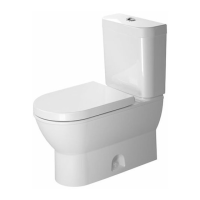
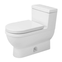
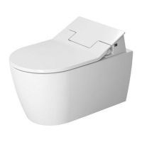
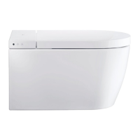
Lists all parts and components included in the product delivery package.
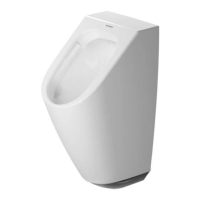
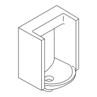
Identifies and illustrates optional accessories that are not supplied with the main product.
Inspect the toilet for any damage incurred during transportation before installation.
Install the shut-off valve and closet flange according to the specified instructions.
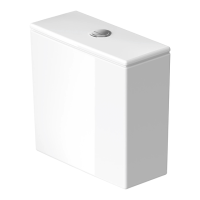
Remove the tank lid to prevent potential damage during the installation process.
Identify the correct water supply line for the market and install any necessary adapters.
Connect the water supply line and rubber gasket, ensuring all connections are securely sealed.
Install the tank bolts and washers to properly secure the tank assembly.
Attach and securely fasten all required hardware to the toilet tank.
Lift the tank onto the toilet bowl and align it correctly for connection.
Attach the tank to the toilet bowl using the provided mounting hardware.
Install the wax ring and T-bolts according to the specific instructions for sealing.
Mount the toilet onto the floor flange, ensuring a watertight seal at the base.
Install washers and nuts to firmly secure the toilet unit to the floor.
Connect the water supply line to the shut-off valve, completing the water hookup.
Turn on the shut-off valve to allow water flow to the toilet tank.
Verify the water level in the tank and adjust it to the proper setting if needed.
Install and securely fasten the tank lid onto the tank assembly.
Flush the toilet multiple times and inspect all connections for leaks and watertight seals.
Cut or break off excess bolts and install the protective caps.
Apply silicone sealant around the base of the toilet for stability and final sealing.
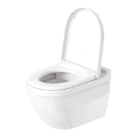
Install the toilet seat and lid according to the specific instructions provided.
Select the appropriate fill valve for your specific toilet model from Type A.
Remove the adjustable screw and unlock the float valve mechanism.
Adjust the float valve to the correct height to set the desired water level.
Lock the float valve securely and reattach the adjustable screw.
Select the appropriate fill valve for your specific toilet model from Type B.
Unlock the float valve by rotating its locking mechanism.
Rotate the valve component to release it from its housing.
Adjust the float valve to the correct height for optimal water filling.
Rotate the valve component back to secure it in the adjusted position.
Lock the float valve into place to complete the adjustment.
Select the appropriate fill valve for your specific toilet model from Type C.
Rotate the guide rod a quarter turn and release it for adjustment.
Slide the clip and adjust the float basket to the correct water level height.
Secure the adjustment clip firmly in its position.
Reattach the components of the fill valve after adjustment.
Lock the guide rod into its final position to complete the adjustment.