Series 1900 Pressure Switch
Specications - Installation and Operating Instructions
Bulletin E-56
Advanced design and precision construction permit these switches to perform many
of the tasks of larger, costlier units. Designed for air conditioning service, they also
serve many uidics, refrigeration, oven and dryer applications. For use with air and
non-combustible gases. Series 1900 Pressure Switches are available with set points
of 0.07 to 20 inches water column. Set point adjustment can be made easily - before or
after installation. Range screw is inside conduit enclosure to help prevent tampering.
For easy mounting and access, pressure and electrical connections and set point
adjustment are located on one side. This permits installation in corners or spaces too
small for other switches.
SPECIAL MODELS & ACCESSORIES
Special close coupled street elbow for right angle pressure connections. Can be
installed on switch anytime. Zinc plated aluminum.
SPECIFICATIONS
Service: Air and non-combustible, compatible gases.
Environment: Standard model intended for indoor use.
Wetted Materials: Consult factory.
Temperature Limits: -30 to 180°F (-34 to 82.2°C) (32°F for non dry air).
Pressure Limits: 45 in w.c. (11.2 kPa) continuous, 10 psig (68.95 kPa) surge.
Humidity Limit: 80% RH (non-condensing).
Altitude Limit: 6560 ft (2000 m) max.
Switch Type: Single-pole double-throw (SPDT).
Repeatability: ±3%.
Electrical Rating: 15 A @ 120-480 VAC (~), 60 Hz. Resistive 1/8 HP @125
VAC(~), 1/4 HP @ 250 VAC(~), 60 Hz. Derate to 10 A for operation at high cycle
rates.
Electrical Connections: 3 screw type, common, normally open and normally
closed.
Installation Category: III (transient over-voltage).
Process Connections: 1/8˝ female NPT.
Mounting Orientation: Diaphragm in vertical position. Consult factory for other
position orientations.
Set Point Adjustment: Screw type inside conduit enclosure.
Pollution Degree: 2.
Weight: 1lb. 4.5 oz. (581 g).
Agency Approvals: CE, UL, CSA, FM.
2-11/32 [59.53]
ø 7/8 [22.23]
CONDUIT
CONNECTION
51/64
[20.24]
2-9/32 [57.94]
2-7/16 [61.90]
1-7/8
[47.63]
1-3/4 [44.45]
CLEARANCE
FOR
COVER REMOVAL
1-19/32
[40.48]
1/8 FEMALE NPT
HIGH PRESSURE
CONNECTION
3
[76.20]
ø 3-1/2
[88.90]
1/8 FEMALE
NPT LOW
PRESSURE
CONNECTION
(2) ø 3/16 [4.76]
MOUNTING
HOLES ON
A 4-3/16
[106.36] B.C.
60° TYP
1-5/16
[33.32]
TYP
41/64
[16.27]
The Dwyer-engineered force-motion amplier increases the leverage of
diaphragm movement and results in a switch with excellent sensitivity and
repeatability.
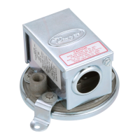
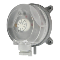
Series 1910 pressure switch. All
pressure and electrical connections
and set point adjustments are on one
side for easy installation.
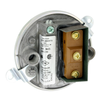
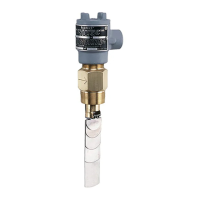
Series 1910 switch with conduit
enclosure off. Shows electric switch
and set point adjustment screw.
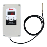
Weatherproof Housing
16 ga. steel enclosure with gasketed cover (NEMA 4) for wet or oily conditions.
Withstands 200 hour salt spray test. Wt. 5 Ibs. (2.3 kg). Switch must be factory installed.
Change 1910 base number to 1911 and add -WP sufx. Example: 1911-1-WP.
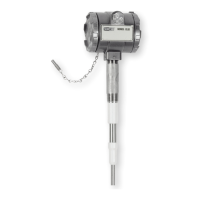
Explosion-Proof Housing
NEMA 7, 9 NEMA 3. (7 lbs). Switch must be factory installed. Change model to 1911
and add -EXPL sufx. Example: 1911-1-EXPL. Aluminum base and cover rated Class
I, Groups C & D, Div. 1. Class II, Groups E, F, & G, Div. 1.
6-1/2 [165.10]
CLEARANCE FOR
COVER REMOVAL
1/2 NPT
PROCESS CONNECTION
3X 1-1/16
[26.99]
6-5/8
[168.28]
3 [76.20]
2X 4-1/4
[107.95]
2X 6-1/8
[155.58]
1/8 FEMALE NPT
LOW PRESSURE
CONNECTION
4X Ø.281
[7.14]
1/8 FEMALE
NPT HIGH PRESSURE
CONNECTION
EXPLANATION OF SYMBOLS
Symbol Publication Description
IEC 60417 - 5032
IEC 60417 - 5019
Alternating current
Protective conductor terminal
SERIES 1910 SWITCHES - MODELS OPERATING RANGES, DEADBANDS
Model
Operating Range,
in w.c.
Approximate Dead Band
At Min. Set Point At Max. Set Point
1910-00
1910-0
1910-1
1910-5
1910-10
1910-20
0.07 to 0.15
0.15 to 0.5
0.40 to 1.6
1.40 to 5.5
3.0 to 11.75
4.0 to 20.0
0.04
0.10
0.15
0.30
0.40
0.40
0.04
0.10
0.16
0.30
0.40
0.50
NC
NO
COM
POWER INPUT
TERMINALS
+ –
GROUNDING
SCREW
~
DWYER INSTRUMENTS, INC.
P.O. BOX 373 • MICHIGAN CITY, INDIANA 46360, U.S.A.
Phone: 219/879-8000
Fax: 219/872-9057
www.dwyer-inst.com
e-mail: info@dwyermail.com
HIGH PRESSURE
CONNECTION 1/8 N.P.T.
LOW PRESSURE
CONNECTION 1/8 N.P.T.
3/4 [19.05]
3/4 [19.05]
1-1/4
[31.75]
3/32
[2.381]
3 [76.20]
3-1/8
[79.38]
5-7/16 [138.1]
4-3/4 [120.7]
4 [101.6]
7/8 [22.22]
1-1/8 [28.58]
1/2 NPT WEATHERPROOF
ELECTRICAL CONNECTION
Ø5/16
[Ø7.938]
3 [76.20]2 [50.80]