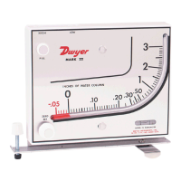
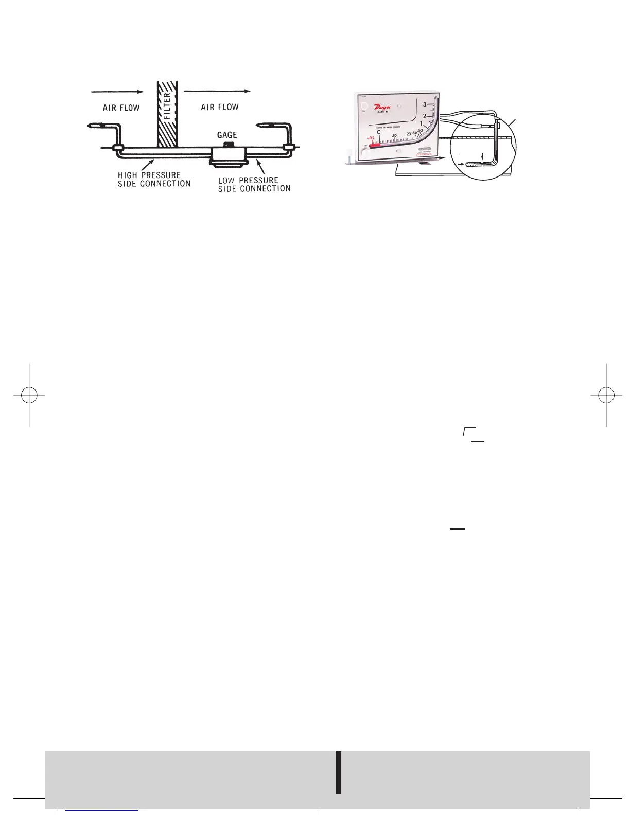
AIR FILTER GAGE
Mount gage within 3 ft. of filter bank. Install
tubing adapters on each side of filter. Run
tubing from clean side of filter to positive
pressure side of gage (left fitting). Run
downstream side to low pressure side of
gage (right fitting). Install green and red
arrows adjacent to indicating tube to indi-
cate filter condition.
AIR VELOCITY METER
A pitot tube should be used for air velocity
readings. Install the pitot tube and gage
carefully to ensure accuracy. Select a loca-
tion for the pitot tube with al least four diam-
eters of smooth straight sections of duct
both upstream and downstream. Install
pitot tube in the center of duct with tip
directed into air stream. Connect the right
angle (leg parallel to tip) to negative (right fit-
ting) and straight pitot tube connection to
positive (left connection) of gage. The veloc-
ity reading shown on the gage is the center
or maximum velocity. For average velocity
across the full area, multiply by a factor of
0.9.
No’s. 27 and 28 require pitot tube at addi-
tional cost. See Bulletin F-41-F.
The velocity indicated is for dry air at 70°F,
29.9˝ barometric pressure and a resulting
density of 0.075 lb/ft
3
. For variation from
these standard conditions, corrections may
be based upon the following data.
AIR VELOCITY CALCULATIONS:
Air Velocity = 1096.2
where Pv = velocity pressure in inches of
water
D = Air density in lb/ft
3
Air Density = 1.325 x
where P
B = Barometric Pressure in inches
of mercury
T = Absolute Temperature (indicat-
ed temperature °F plus 460)
Flow in cu. ft. per min. = Duct area in square
feet x air velocity in ft. per min.
PITOT TUBE SENSES TOTAL AND STATIC PRESSURES. MANOMETER
MEASURES VELOCITY PRESSURE-(DIFFERENCE BETWEEN TOTAL AND
STATIC PRESSURES).
PB
T
Pv
D
√
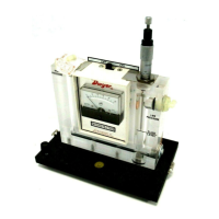
APPLICATIONS MARK II MANOMETER
DWYER INSTRUMENTS, INC.
Phone: 219/879-8000 www.dwyer-inst.com
P.O. BOX 373 • MICHIGAN CITY, INDIANA 46361, U.S.A. Fax: 219/872-9057 e-mail: info@dwyer-inst.com
©Copyright 2004 Dwyer Instruments, Inc.
FR# 67-440215-00 Rev. 11
Printed in U.S.A. 1/04