EasyManua.ls Logo

Dwyer Instruments 25 User Manual

Dwyer Instruments 25
4 pages
To Next Page IconTo Next Page
Page #1 background imageLoading...
Page #1 background image
Dwyer Mark II Manometers come in a vari-
ety of ranges. Make sure the oil being used
is for the correct manometer.
Mark II #25, 27, MM-80 and M-700 Pa use
red gage oil (specific gravity 0.826).
Mark II #26, 28 and MM180 use blue gage
oil (specific gravity 1.9).
If additional oil is required, call or fax nearest
Dwyer office listed at bottom of page.
INSTALLATION
Position manometer on a vertical surface.
Drill two 1/8˝ or 9/64˝ holes on a vertical line
315/16˝ apart. Loosely mount manometer
with self-tapping screws provided. Adjust
gage until level bubble is centered in level
vial, then secure the manometer tightly.
For portable use, order optional A-612
Portable Stand.
FILLING
Turn the zero set knob counterclockwise until
it stops, then turn clockwise 3 full turns. This
puts zero in approximately the middle of the
travel adjustment in either direction. Remove
the fill plug and fill with gage fluid until fluid
reaches zero on scale. Minor adjustments
can be made to adjust zero by adjusting zero
knob. Replace fill plug. If gage is overfilled,
remove excess by inserting pipe cleaner
through the fill port to blot up excess oil.
MAINTENANCE
Check oil level regularly and adjust zero with
zero adjust knob. Be sure tubing connec-
tions are disconnected and gage is open to
atmosphere before adjusting zero.
Clean with mild soap and water. Avoid any
cleaning fluids which may result in damaging
the gage.
ACCESSORIES
Each Mark II manometer includes two tubing
connectors for 1/8˝ pipe or sheet metal
ducts, two mounting screws, 3/4 oz. bottle
of indicating fluid, red and green pointer
flags, 8´ of double column tubing and instruc-
tions.
Mark II Series Molded Plastic Manometers
Specifications - Instructions and Operation
Bulletin D-58
DWYER INSTRUMENTS, INC.
Phone: 219/879-8000 www.dwyer-inst.com
P.O. BOX 373 • MICHIGAN CITY, INDIANA 46361, U.S.A. Fax: 219/872-9057 e-mail: info@dwyer-inst.com
Mark II Model No. 25
inclined-vertical manometer,
(shown with optional A-612 portable stand)
D-58 1/27/04 12:01 PM Page 1
Question and Answer IconNeed help?

Do you have a question about the Dwyer Instruments 25 and is the answer not in the manual?

Dwyer Instruments 25 Specifications

General IconGeneral
Model25
CategoryMeasuring Instruments
ManufacturerDwyer Instruments
ServiceAir and compatible gases
Temperature Limits20 to 140°F (-6.67 to 60°C)
Process Connections1/8" female NPT
Size4" (101.6 mm) diameter
Mounting OrientationVertical
Housing MaterialDie cast aluminum

Summary

Mark II Series Molded Plastic Manometers

Specifications and Operation Overview

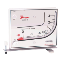
General information on the Mark II series manometers and their operational purpose.

Installation Procedure

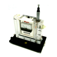
Detailed steps for mounting the manometer on a vertical surface, ensuring it is level.

Filling and Zeroing

Instructions for filling the manometer with fluid and setting the initial zero point.

Maintenance and Cleaning

Routine checks for oil level, zero adjustment, and cleaning with mild soap and water.

Included Accessories

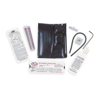
List of items included with each Mark II manometer, such as tubing connectors and fluid.

Applications and Air Velocity

Air Filter Gage Use

Guidance on using the manometer to monitor air filter condition by connecting to ductwork.

Air Velocity Measurement

Instructions for using a pitot tube to measure air velocity in ducts, including placement.

Air Velocity Calculations

Formulas and steps for calculating air velocity and density from various pressure and temperature inputs.

Related product manuals