EasyManua.ls Logo

Dwyer Instruments Magnehelic 2000 Series User Manual

Dwyer Instruments Magnehelic 2000 Series
6 pages
To Next Page IconTo Next Page
Page #1 background imageLoading...
Page #1 background image
BULLETIN NO.A-27
Magnehelic
®
Differential Pressure Gage
OPERATING INSTRUCTIONS
SPECIFICATIONS
Dimensions: 4-3/4 dia. x 2-3/16 deep.
Weight: 1 lb. 2 oz.
Finished: Baked dark gray enamel.
Connections: 1/8NPT high and low pressure
taps, duplicated, one pair side and one
pair back.
Accuracy: Plus or minus 2% of full scale, at
70°F. (Model 2000-0, 3%; 2000-00, 4%).
Pressure Rating: 15 PSI (0,35 bar)
Ambient Temperature Range: 20° to 140°F
(-7 to 60°C).
Standard gage accessories include two 1/8
NPT plugs for duplicate pressure taps,
two 1/8 NPT pipe thread to rubber tubing
adapters, and three flush mounting
adapters with screws.
Caution: For use with air or compatible
gases only.
For repeated over-ranging or high cycle rates,
contact factory.
Not for use with Hydrogen gas. Dangerous
reactions will occur.
DWYER INSTRUMENTS, INC.
P.O. BOX 373 • MICHIGAN CITY, INDIANA 46361 U.S.A.
Phone: 219/879-8000 www.dwyer-inst.com
Fax: 219/872-9057 e-mail: info@dwyer-inst.com
Lit-by-Fax: 888/891-4963
11/16
[17.46]
1/8 NPT LOW
PRESSURE
7/16
[11.11]
1-11/16
[42.86]
1/2
[12.70]
1/8 NPT LOW
PRESSURE
1/8 NPT HIGH
PRESSURE
1/2
[12.70]
1/8 NPT HIGH
PRESSURE
Ø4-1/8 [104.78] BOLT
CIRCLE FOR PANEL MOUNTING
120° APART
1-1/4
[31.75]
Ø4-3/4
[120.65]
1-3/4
[44.45]
Question and Answer IconNeed help?

Do you have a question about the Dwyer Instruments Magnehelic 2000 Series and is the answer not in the manual?

Dwyer Instruments Magnehelic 2000 Series Specifications

General IconGeneral
Model Series2000
ServiceAir and compatible gases
Connection Size1/8" NPT
TypeDifferential Pressure Gauge
Accuracy±2% full scale
Case MaterialDie cast aluminum
Process Connections1/8" NPT female
Connection LocationRear
MaterialAluminum

Summary

Magnehelic Differential Pressure Gage Installation

Surface Mounting

Locates mounting holes 120° apart on a 4-1/8" dia. circle and uses No. 6-32 machine screws.

Flush Mounting

Requires a 4-9/16" dia. opening for panel insertion and securing with screws.

Zeroing the Gage

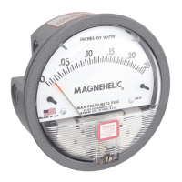
Sets the indicating pointer to the zero mark using the external zero adjustment screw on the cover.

Operation

Connects tubing for positive, negative, or differential pressure measurement to appropriate ports.

Ordering Instructions

Advise including model number, pressure range, and special options when contacting the factory.

Magnehelic Gage Maintenance and Troubleshooting

Maintenance Overview

No lubrication or periodic servicing required. Keep case clean and vent lines occasionally.

Calibration Check

Compares Magnehelic gage readings with a second gage or manometer of known accuracy.

Field Calibration

Procedure involves loosening bezel, removing cover, adjusting clamp, and reassembling.

Troubleshooting Common Issues

Addresses issues like sluggish indication, stuck pointers, and provides solutions.

Related product manuals