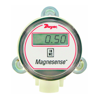
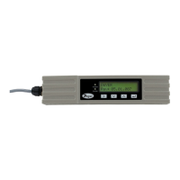
The Series MS Magnesense
®
Differential Pressure Transmitter is an
extremely versatile transmitter for monitoring pressure and air velocity.
This compact package is loaded with features such as: field selectable
English or metric ranges, field upgradeable LCD display, adjustable
dampening of output signal (with optional display) and the ability to
select a square root output for use with pitot tubes and other similar flow
sensors.
Along with these features, magnetic sensing technology provides
exceptional long term performance and enables the Magnesense
®
Differential Pressure Transmitter to be the solution for a myriad of
pressure and air flow applications.
INSTALLATION
Mounting:
The transmitter should be mounted on a vertical surface with the
connections directed down to prevent moisture from entering either the
pressure ports or the electrical cable entry. The diaphragm must be
vertical to minimize gravity effects on the diaphragm.
Mount the transmitter using #8 x 1/2˝ pan head sheet metal screws in the
mounting flanges. Do not over tighten.
Duct Mount:
The transmitter should be mounted away from fans, corners, heating
and cooling coils and other equipment that will effect the measurement
of the pressure.
1. To mount the transmitter, drill a .562 (12.70) diameter hold into the
duct.
2. Insert transmitter probe into the duct.
3. Mark location of three mounting holes on duct using mounting flange
as template. Drill holes.
4. Attach mounting flange to duct with (3) #8 x 1/2 pan head sheet metal
screws. Do not overtighten screws.
Electrical Connection:
2-Wire Operation:
Series MS Magnesense
®
Differential Pressure Transmitter
Specifications - Installation and Operating Instructions
Bulletin A-26
SPECIFICATIONS
Service: Air and non-combustible, compatible gases.
Wetted Materials: Consult factory.
Accuracy: ±1% for 0.25˝ (50 Pa), 0.5˝ (100 Pa), 2˝ (500 Pa), 5˝ (1250
Pa), ±2% for 0.1˝ (25 Pa), 1˝ (250 Pa) and all bi-directional ranges.
Stability: ±1% F.S./ year.
Temperature Limits: 0 to 150°F (-18 to 66°C).
Pressure Limits: 1 psi (6.89 kPa) maximum, operation; 10 psi (68.9
kPa) burst.
Power Requirements: 2-wire, 10 to 35 VDC; 3-wire, 17 to 36 VDC or
isolated 21.6 to 33 VAC.
Output Signals: 2-wire, 4 to 20 mA; 3-wire, 0 to 10 V or 0 to 5 V.
Response Time: Adjustable 0.5 to 15 sec. time constant. Provides a
95% response time of 1.5 to 45 seconds.
Zero & Span Adjustments: Digital push button.
Loop Resistance: Current output: 0-1250 ohm max; Voltage output:
min. load resistance 1 k ohmΩ.
Current Consumption: 40 mA max.
Display (optional): 4 digit LCD.
Electrical Connections: 4 to 20 mA units: 2-Wire: European style
terminal block for 16 to 26 AWG; 0 to 10 V units: 3-Wire: European
style terminal block 16 to 22 AWG.
Electrical Entry: 1/2˝ NPS thread.
Accessory: A-151 cable gland for 5 to 10 mm diameter cable.
Process Connections: 3/16˝ (5 mm) ID tubing. Maximum
OD 9 mm.
Enclosure Rating: NEMA 4X (IP65).
Mounting Orientation: Diaphragm in vertical position.
Weight: 8.0 oz (230 g).
Agency Approval: CE.
The following standards were used for CE approval:
CENELEC EN 61000-4-2: 2001
CENELEC EN 61000-4-3: 2002
CENELEC EN 61000-4-4: 1995
CENELEC EN 61000-4-5: 2001
CENELEC EN 61000-4-6: 2003
CENELEC EN 61000-4-8: 2001
CENELEC EN 55011: 2003
CENELEC EN 61326: 2002
89/336/EED EMC Directive
Ø3-7/16
[Ø87.31]
2
-41/64
[
67.07]
1
/2 NPT
21/32
[16.67]
2
1/32
[
16.67]
29/32
[23.02]
1/2
[12.70]
5
7/64
[
22.62]
(
3) 3/16 [4.76] HOLES
E
QUALLY SPACED ON A
4
.115 [104.52] BC
2
-11/64
[
55.17]
2-9/16
[65.09]
8-1/8
[206.38]
Ø
35/84 [13.87]
DO NOT EXCEED SPECIFIED SUPPLY VOLTAGE RATINGS.
PERMANENT DAMAGE NOT COVERED BY WARRANTY
WILL RESULT. 2-WIRE UNITS ARE NOT DESIGNED FOR AC VOLTAGE
OPERATION.
CAUTION
ø3-7/16
[Ø87.31]
1/2 NPT
2
5/64
[
9.96]
1-41/64
[41.71]
2-41/64
[67.24]
21/32
[16.67]
5
7/64
[22.62]
2
1/32
[
16.67]
2
9/32
[
23.02]
1
/2
[
12.70]
2-11/64
[55.17]
3
-11/32
[
84.84]
3-1/2
[88.90]
Wall Mount Bracket
DIN Mount Bracket
DWYER INSTRUMENTS, INC.
Phone: 219/879-8000 www.dwyer-inst.com
P.O. BOX 373 • MICHIGAN CITY, INDIANA 46360, U.S.A. Fax: 219/872-9057 e-mail: info@dwyer-inst.com