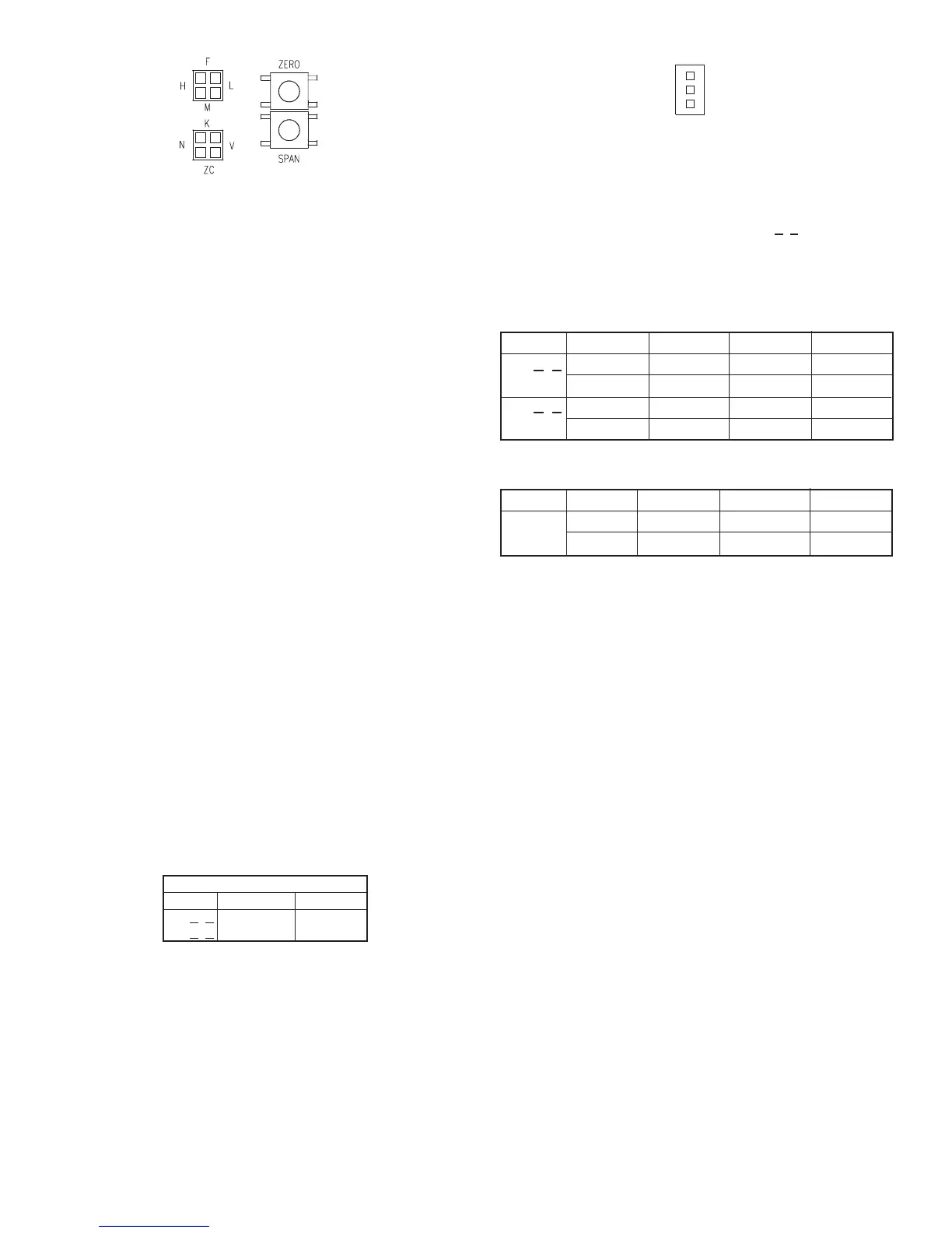
Figure 5: Mode and Range Programming
Jumpers and Switches
Jumper block PJ3’s primary function is to control when the unit is in the
High, Medium or Low range. Each unit has three user selectable
operating ranges for what input pressure corresponds to full scale of the
analog output. When the left two pins on PJ3 next to the letter “H” are
shorted together by the supplied shorting jumper, the device’s full scale
analog output corresponds to the highest pressure range of the unit.
When the shorting jumper shorts the bottom two jumpers next to the
letter “M” of PJ3, the full scale analog output corresponds to the middle
range of the unit. Similarly the low range is selected by placing the
shorting jumper on the pins of PJ3 next to the letter “L”. The jumper for
PJ3 is factory installed to the high range. If no jumper is installed on PJ3,
the device defaults to the “H” range selection.
Jumper block PJ5’s primary function is to control the operating mode.
There are three operating modes, Normal, zero center and Velocity. The
Normal operating mode provides for zero pressure to correspond to 0 V
or 4 mA output. This mode is selected by placing the supplied shorting
jumper for PJ5 on the pins next to the letter “N”. The jumper for PJ5 is
factory installed to the Normal Mode on standard units. If no jumper is
installed on PJ5, the device defaults to the “N” selection.
On factory ordered bi-directional units, the PJ5 jumper will come from the
factory in the ZC or Zero-Center position.
The Zero Center operating mode provides for zero pressure to
correspond to 2.5 V, 5 V or 12 mA while the selected full scale range
corresponds to 5 V, 10 V or 20 mA current. Negative full scale pressure
is required to go to 0 V or 4.0 mA.
The Velocity mode provides the ability for the unit in conjunction with a
pitot tube or similar flow sensor with known K factor to give a direct
output in air velocity. This mode is selected by placing the supplied
shorting jumper for PJ5 on the pins next to the letter “V”. The Velocity
mode overrides the High, Middle, and Low range setting on PJ3 and
forces the unit to the High range setting. If the optional display is present,
this mode prompts the display to read in air velocity. The current or
voltage output is modified such that full scale output is 4004* K* √(∆P)
feet per minute or its metric equivalent in meters per second depending
upon which units are selected. The factory programming for the K factor
is 1.00 but may be adjusted (see Adjust K Factor). The velocity displayed
for the various models can be found in Table 1.
Table 1
SETUP
Set Measurement Units:
Magnesense
®
transmitters can be easily set to operate in either English
or metric units.
The programming jumper is PJ7 and is located in the upper half of the
board and under the LCD display if the LCD is present. A representation
of this jumper is shown in Fig. 6. English units are selected by placing the
provided shorting jumper on the lower two pins of the block next to the
label “H2O”. Metric units are selected by placing the provided shorting
jumper on the upper two pins of the block next to the label “Pa”. If no
jumper is present English units are selected by default.
F
igure 6: Measurement Units Programming Jumper
In addition to the obvious change in the scale of the LCD display, the full
scale range and corresponding analog outputs are also affected by the
measurement units selection. The analog output goes to full scale output
(5 volts, 10 volts or 20 mA depending on model) of the selected range
and units. See Table 2. For example on Model MS-X2X, when high range
and English units are selected full scale output occurs at 0.5 in w.c.
(124.5 Pa). When high range and metric units are selected, analog full
scale output is at 100 Pa (0.4015 in w.c.).
FULL SCALE ANALOG OUTPUT
STANDARD MODELS
Table 2
Zero Center Models
Install Optional Display:
The A-435 LCD conversion kit allows any non display model to have the
LCD added at a later time. The kit contains an LCD display and
replacement cover with LCD window. The optional display may be set to
read pressure either in inches water column or pascal. The optional
display can be also set to display air velocity in feet per minute or meters
per second when used with a pitot tube or similar flow sensor with a
known K factor.
The optional display for the Magnesense
®
transmitter is mounted on the
main board by connectors PJ1 and PJ2. The display is properly mounted
when PJ1 and PJ2 on the display are connected to the corresponding
PJ1 and PJ2 on the main board. See Fig. 4. Installing the display upside
down causes no harm to the display or the main board. The display just
simply reads upside down.
When upgrading a Magnesense
®
transmitter with an A-435 display kit, it
is important to note that it is possible for a device to have been user
calibrated to appear properly calibrated at the analog output while in fact,
it has been improperly calibrated. This can be done by improperly
calibrating the analog output’s zero and span and then using the
pressure zero and span to compensate for the improperly calibrated
analog output. This possibility can be eliminated by checking that the
analog output’s zero calibration is either 0 V or 4 mA and the analog
output’s full scale calibration is either 10 V or 20 mA output. See the User
Calibration section for details on how to perform these tests.
Label Display (Optional):
The optional LCD display does not contain engineering unit indication.
So that the display may be appropriately marked, four adhesive labels
have been provided with the units. The unit labels are IN W.C., Pa, fpm,
and M/S. Attach the appropriate provided units label above the display
window on the cover of the device to indicate to which units the display
has been set.
Low
0.1 in w.c.
25 Pa
1 in w.c.
250 Pa
Medium
0.25 in w.c.
50 Pa
2 in w.c.
500 Pa
High
0.5 in w.c.
100 Pa
5 in w.c.
1250 Pa
English
Metric
English
Metric
Model
MS-X
2X
MS-X1X
Low
±0.1 in w.c.
±25 Pa
Medium
±0.25 in w.c.
±50 Pa
High
±0.5 in w.c.
±100 Pa
English
Metric
Model
MS-021
MS-221
Model
MS-X2X
MS-X1X
English
K* 2830 fpm
K* 8950 fpm
Metric
K* 14.4 m/s
K* 45.5 m/s
Velocity Displayed
 Loading...