Electrical Connection:
2-Wire Operation, continued:
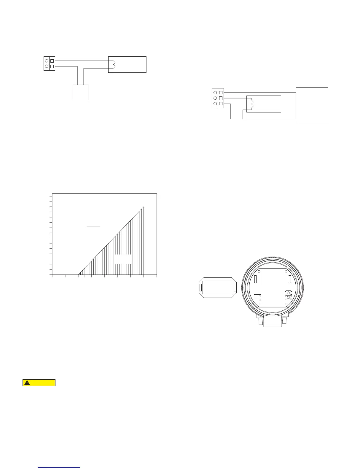
The connections to the transmitter are made through a two circuit
European style terminal block TB1 located at the bottom left of the main
PB board. Polarity is indicated by + and – signs on the P.C. board.
Figure 1
An external power supply delivering 10 to 35 VDC with a minimum
current capability of 40 milliamps must be used to power the control loop
in which the Magnesense
®
transmitter is connected. Refer to Fig. 1 for
connection of the power supply, transmitter and receiver. The range of
appropriate receiver load resistances (R
L
) for the power supply voltage
available is given by the formula and graph in Fig. 2. Shielded two wire
cable is recommended for control loop wiring and the negative side of the
loop may be grounded if desired. Note also that the receiver may be
connected in either the negative or positive side of the loop, whichever is
most convenient. Should polarity of the transmitter or receiver be
inadvertently reversed, the loop will not function properly but no damage
will be done to the transmitter.
Figure 2
The maximum length of connecting wire between the transmitter and the
receiver is a function of wire size and receiver resistance. That portion of
the total current loop resistance represented by the resistance of the
connecting wires themselves should not exceed 10% of the receiver
resistance. For extremely long runs (over 1,000 feet), it is desirable to
select receivers with higher resistances in order to keep the size and cost
of the connecting leads as low as possible. In installations where the
connecting run is no more than 100 feet, connecting lead wire as small
as No. 22 Ga. can be used.
3-Wire Operation:
The connections to the transmitter are made through a three circuit
European style terminal block. Connect the power and signal leads to the
corresponding terminals as shown in Fig. 3. When using a DC supply,
the positive of the supply should be connected to V+ and the negative
connected to Com. Connecting the leads in reverse will not damage the
device but it will not operate. The DC supply should be capable of
providing 20 mA or more of current per Magnesense
®
transmitter.
When using an isolated AC supply, either leads of the supply may be
connected to Com and V+. The input diode of the device half wave
rectifies and filters the applied AC voltage. A small DC current of less
than 20 mA is thus drawn through the transformer. The transformer used
for the AC supply must be capable of handling this small DC current. Use
a UL 1584 Class 2 rated transformer rated between 24 V and 30 VAC,
40 VA or larger, 50/60 Hz. UL 1584 Class 2 rated transformers are limited
to 30 VAC maximum under any conditions at nominal line. The AC input
voltage to the device is thus limited to a minimum of 21.6 at low line (24
V-10%) and 33 V at high line (30 V+10%).
Figure 3
The output of Vo is 0 to 10 VDC or 0 to 5 VDC depending on model. As
much as 10 mA may be drawn from Vo without affecting accuracy. This
limits the minimum load RL connected to Vo to 1 KΩ or higher.
Remember to keep the wiring resistance between the output and the
receiver R
L
low compared to value of R
L
. While the voltage at the
terminals remains unchanged with a 10 mA current flow, resistive losses
in the wiring do cause errors in the voltage delivered to R
L
. For a 1%
accurate gauge, a good rule of thumb would be to keep the resistance of
the leads less than 0.1% of the value of R
L
. This will keep the error
caused by current flow below 0.1%.
To minimize noise in the signal use shielded cable. The common line
may also be grounded.
Pressure Connections
Two integral tubing connectors are provided. They are designed to fit
3/16˝ (5 mm) ID tubing. Connect the high pressure to the High side as
shown in Fig. 4. Be sure the pressure ratings of the tubing exceed that
of the operating ranges.
Figure 4
Select Operation Mode and Range:
The operating modes and ranges are controlled by two shorting jumpers
on a pair of jumper blocks, PJ3 and PJ5. These two jumper blocks are
shown in Fig. 5.
RECEIVER
R
L
TB1
–
+
+
–
POWER
SUPPLY
10-35V
POWER SUPPLY VOLTAGE
0
5101315
20 25 30 35 40
MAXIMUM VALUE (1250 W )
OPERATING
REGION
TOTAL RECEIVER RESISTANCE (W )
RL MAX =
V
ps - 10.0
20mA DC
1500
1400
1300
1200
1100
1000
900
8
00
7
00
600
500
400
300
200
100
50
POWER SUPPLY
17 TO 36 VDC
O
R
2
1.6 TO 33 VAC
R
ECEIVER
TB1
V
+
V
o
COM
R
L
PJ1 PJ2
PJ2
P
J1
S
W1
SW2
TB1
HIGH
LOW
DO NOT EXCEED SPECIFIED SUPPLY VOLTAGE RATINGS.
PERMANENT DAMAGE NOT COVERED BY WARRANTY
WILL RESULT.
CAUTION
 Loading...