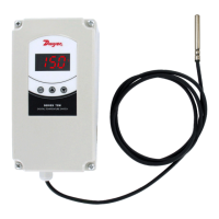
DESCRIPTION
Monitor and control temperature for heating and cooling applica-
tions with the Series TS2 Digital Temperature Switch. The Series
TS2 offers twelve programmable functions to customize the unit to
fit application requirements. Use the 15(5) Amp SPDT relay output
to drive a motor, compressor, or fan. Designed with the OEM in
mind, the TS2 offers the ability to configure multiple units with the
touch of a button.
Programming multiple units is quick and easy. Simply program one
switch with the desired parameter settings and connect the config-
uration key (sold separately) to the back of the unit. Press the but-
ton on the configuration key and download the parameter settings.
Connect the key to the other switches to upload the stored settings
with the push of a button.
The TS2 features set point adjustments, static defrost timing, com-
pressor mean time, hysteresis, and ambient probe adjustment.
Security protection is offered using a password code. The Series
TS2 Digital Temperature Switches are designed to operate with PTC
(1000Ω @ 25°C) probes sold separately.
INSTALLATION
The thermostat must be installed by authorized professionals. It
should be located in a place free of vibrations, impacts, water and
corrosive gases.
A hole measuring 71 x 29 mm must be cut in the panel where the
thermostat is to be fitted (apply silicone to make it leaktight). Then,
the fixing cups must be fitted, sliding them onto the thermostat until
secure. Do not force tightening of the screw if the U-brackets are
used. The connections must be covered with the rear cover for this.
WIRING INSTRUCTIONS
Avoid installing the probe’s cables in proximity with any power
cable. If the length of the probe cables measures more than 100
meters, a recalibration adjustment must be made (parameter P1).
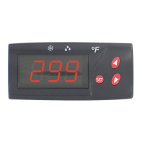
FRONT OPERATION
PUSH BUTTONS
Pushing SET once gives access to the SP. Pushing for 8
seconds gives way to the requested code. After entering
the correct code, all parameters are accessible. This but-
ton alternates between text parameters and their value. It
validates the modified parameters. When pressed with
DOWN, it exits parameter programming.
Pressing this arrow allows the user to go to the next
parameter or increase the value viewed on the display.
When pressed for 8 seconds, it activates or deactivates
defrosting.
Pressing this arrow allows the user to go to the previous
parameter or decreases the value viewed on the display.
When pressed for 8 seconds, it activates or deactivates the
continuous cooling cycle. When pressed simultaneously
with SET, it exits the programming mode.
PROGRAMMING PARAMETERS
Access only to Set Point SP (without code protection):
•Press and release SET. SP text appears on the display.
•Press SET again. The real value is shown on the display.
•Modify the value using the UP and DOWN keys.
•Press SET and DOWN to quit programming, or wait 1 minute for
Series TS2- Digital Temperature Switch
Specifications - Installation and Operating Instructions
Bulletin T-TS2
SPECIFICATIONS
Probe Range: -58 to 302°F (-50° to 150°C).
Input: PTC thermistor 1000Ω @ 25°C.
Output: 15A PTC SPDT relay @ 250 VAC resistive, 5A inductive.
Horsepower Rating (HP): 3/4 HP.
Control Type: ON/OFF.
Power Requirements: 110 VAC.
Accuracy: ±1°C.
Display: 3-digit, Red, 1/2˝ digits.
Resolution: ±1 digit.
Memory Backup: Nonvolatile memory.
Ambient Operating Temperature: 14 to 158°F (-10 to 70°C).
Storage Temperature: -4 to 176°F (-20° to 80°C).
Weight: 2.3 oz (65 g).
Front Panel Rating: IP64.
Agency Approvals: CE, URc, UR.
250 VAC 15(5)A 30 LRA
Power
Supply
OUTPUT
7
89
10
11
1
2
Probe Input
t°
(3.000)
(1.338)
(2.375)
(1.100)
T-TS2 12/8/06 10:03 AM Page 1