DWYER INSTRUMENTS, INC.
Phone: 219/879-8000 www.dwyer-inst.com
P.O. BOX 373 • MICHIGAN CITY, INDIANA 46361, U.S.A. Fax: 219/872-9057 e-mail: info@dwyer-inst.com
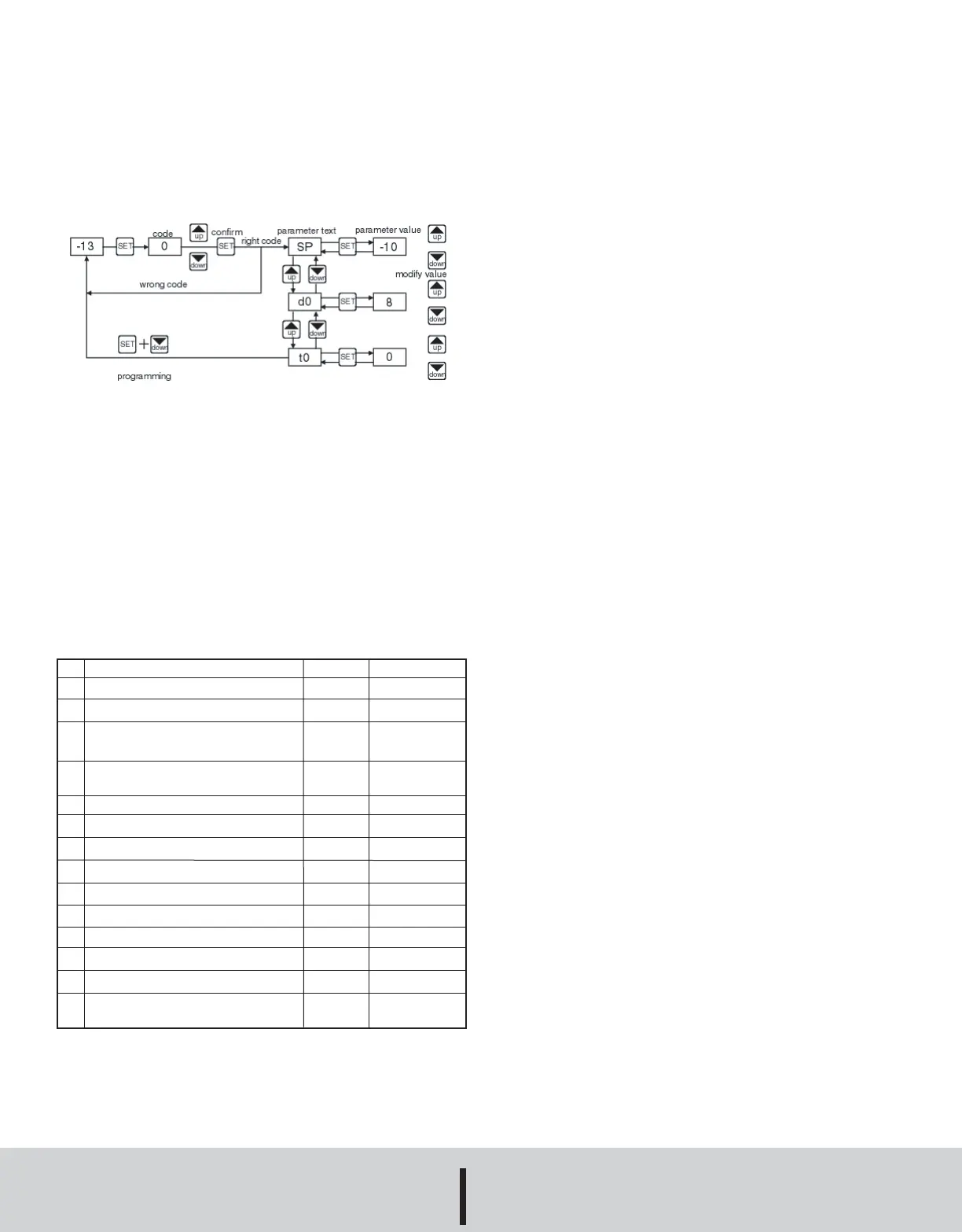
•Press SET to enter the code. If it is correct, the first parameter label will
be shown on the display (SP).
•Move to the desired parameter with the UP and DOWN keys.
•Press SET to see the value.
•Modify the value with the UP and DOWN keys.
•Press SET to enter it, and exit to text parameter.
•Press SET and DOWN to quit programming, or wait 1 minute for the
TIMEOUT.
SETTING THE KEYBOARD CODE TO ZERO
The keyboard code can be set to zero by holding the SET key and turn-
ing the controller off then on again.
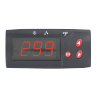
LED INDICATIONS
Out: This indicates that the compressor is connected. It waits the pro-
grammed minimum stop time of the compressor.
Def: This indicates that defrosting is activated.
MESSAGES DISPLAY
In normal operation, the probe temperature will be shown. In case of
alarm or error, the following messages will be shown:
• Er- Memory error.
• -- Short-circuited probe error.
• oo- Open probe error.
PARAMETERS
PARAMETER DESCRIPTIONS
SP = Set Point. Temperature wished to regulate the machine. Can vary
from r1 to r2.
r0 = Differential. Heating: If temperature is ≥ Set then out OFF. If tem-
perature is ≤ Set then out OFF. Cooling: if temperature is > Set + r0 then
out ON. If temperature is ≤ Set then out OFF.
r1 = Lower Set Point Limit
r2 = Higher Set Point Limit
d0 = Heat or Cooling Control. Ht = heating control, Co = cooling con-
trol.
d2 = Defrosting Time Remaining, in minutes. If d2 = 0, defrosting will
not start.
d8 = Interval Between Two Defrostings, in hours.
c0 = Minimum time for compressor to be OFF. Minimum time from
when the compressor stops till it connects again.
c1 = Continuous Cycle Time. The remaining time for a continuous cold
cycle.
c2 = ON time of fault cycle, during probe error.
c3 = OFF time of fault cycle, during probe error.
P1 = Ambient Probe Calibration. Offsets degrees to adjust the ambient
probe.
H5 = Access Code to Parameters. Factory-set as 00.
t0 = Temperature Display Limit. Maximum temperature shown on the
display, although the real temperature can be greater.
OPERATION IN CASE OF ERROR
If the probe or thermostat memory should fail, the compressor will be con-
nected for 5 minutes ON then 5 minutes OFF.
MAINTENANCE
CLEANING
Clean the surface of the display controller with a soft, damp cloth. Never
use abrasive detergents, petrol, alcohol or solvents.
REPAIRS
After final installation of the TS Series Digital Temperature Switch, no rou-
tine maintenance is required. A periodic check of system calibration is rec-
ommended. The devices are not field repairable and should be returned
to the factory if recalibration or other service is required. After first obtain-
ing a Returned Goods Authorization (RGA) number, send the material,
freight prepaid, to the following address. Please include a clear
description of the problem plus any application information
available.
Dwyer Instruments,Inc.
Attn: Repair Department
102 Highway 212
Michigan City, IN 46360 U.S.A
SP
r0
r1
r2
d0
d2
d8
c0
c1
c2
c3
P1
H5
t0
Description
Set point
Differential or hysteresis
Lower value for set point
Higher value for set point
Heating or cooling control
Time for defrosting
Interval time between defrosting
Minimum stop time for compressor
Continuous cycle time
ON time of fault cycle
OFF time of fault cycle
Ambient probe adjustment
Parameter access code
Maximum temperature on display
Units
degrees
degrees
degrees
degrees
option
minutes
hours
minutes
hours
minutes
minutes
degrees
numeric
degrees
Range
r1 to r2
1 to 20°
-50 to 150°C
-50 to 302°F
-50 to 150°C
-50 to 302°F
Ht/Co
0 to 59’
0 to 24
0 to 59’
0 to 24
0 to 999
0 to 999
-10° to 10°
0 to 99
-50 to 150°C
-50 to 302°F
exits
©Copyright 2009 Dwyer Instruments, Inc. Printed in U.S.A. 8/09 FR# R7-443771-00 Rev.1
T-TS2:TS2 Bulletin 8/13/09 12:00 PM Page 2
 Loading...