19
RTR-2 Installation
Please read the following section carefully.
The best location for this unit is at the operating position with easy access to the controls since you
will be using the S-Meter and listening to your receiver while operating the RTR-2 mode switch.
Connections
Make connections to the RTR-2 as follows:
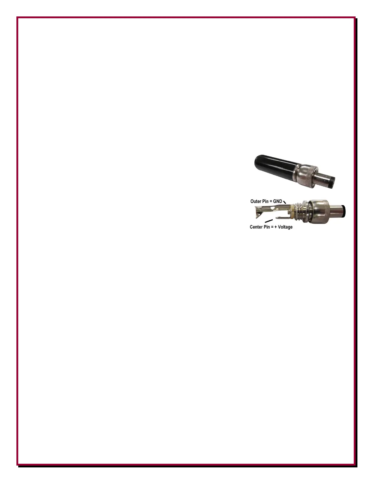
Connect a well filtered and fused power source of +13.8 to
+21 Vdc 2A minimum to the 2.1 mm center (positive)
MAIN PWR jack using the included 2.1 mm screw-in plug.
A standard 2.1 mm plug will also work. Well filtered and
fused station power is recommended. For most operations
(no loops or special receive antennas) using your shack
power of +13.8 Vdc is fine. Be aware that any voltage
used as an input to the RTR-2 (+13.8 to +21 Vdc) will be
fed by the bias tee circuitry onto the RX ANT port. Some
active antennas may require specific voltage levels to work
properly. You have to account for line loss over long distances as well. Depending on your
installation, you may need to use an external voltage inserter (Bias Tee) to provide different
feedline voltage.
Connect a receiving antenna to the RX ANT IN BNC or F connector.
Connect a standard shielded RCA male patch cable between the RADIO PTT Phono
connector and a transceiver. For Kenwood transceivers, use the optional DXE-KWD-RTR
cable.
Connect the RADIO jack to a transceiver antenna jack for use on radios that lack a RX ANT
IN or the transceiver receive-only antenna port, or receiver antenna input.
Once all connections have been made and double checked, with DC power turned on, and
connected (with the RTR-2 turned off, the POWER LED will be yellow. Turning POWER ON,
the POWER ON LED will change to green.
The three position MAIN ON - RX ANT - MAIN ON toggle switch for manual control of the
DXE-RTR-2 antenna selections.
MAIN ANT (toggle switch up)
Manually switches the transceiver (RADIO) to the MAIN ANT for receiving with the
transmitting antenna. The transceiver will remain connected to MAIN ANT during transmit.
The mode LED will illuminate red.