25
Additional System Configurations
Diagram 4 shows the legacy receiving application which is similar to the NCC-2 with active
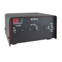
receive antennas. The DXE-RTR-2 Receive Antenna Interface for Transceivers now allows owners
of transceivers which lack a receive antenna input to use a phased receive antenna array. This
diagram shows the connections for use of the DXE-AAPS3-1P Electronically Rotatable Receive
Antenna System, which consists of two active receive vertical antennas and the DXE-NCC-1
Receive Antenna Variable Phasing Controller using the DXE-RTR-2 Receive Transmit Relay.
Diagram 5 includes the exceptional DXE-RPA-2-PM Receive Preamplifier Plug-In Module with
the main (transmit) antenna. For many years Amateurs have been requesting a method to employ a
receiving device on their transceivers which lack a built-in preamplifier. The DXE-RTR-2 provides
this connection option. Instantaneous receive comparisons between 'preamplifier in' and
'preamplifier out' are easily accomplished using the DXE-RTR-2 MAIN ANT - RX ANT - MAIN
ANT toggle switch.
Diagram 6 demonstrates another common use for the DXE-RTR-2 and the connections required
for use of a two direction DXE-RBSA-1P Reversible Beverage Antenna System.
Diagram 7 shows how a DXE-RFS-SYS-4P Complete Receive Four Square Array Package
connected to a transceiver that does not offer a receive antenna input.
Diagram 8 demonstrates how the DXE-RTR-2 may be used in a classic T/R relay application with
an added bonus! The popular optional accessory for older receivers, the DX Engineering Receive
Preamplifier model DXE-RPA-2, may be used externally, for improving older receiver sensitivity of
the transmit antenna, especially on higher frequencies. When the pre-amp is not required, it may be
internally bypassed by removing the DC power to it. (The RTR-2 option slots are not used).
Set the MAIN ANT - RX ANT - MAIN ANT toggle switch to the RX ANT (center) position to
connect the MAIN ANT to your receiver. When you key the transmitter, the DXE-RTR-2's
automatic 4 ms changeover from receive to transmit switches the MAIN ANT to the transmitter.
Manually switching the toggle switch to the MAIN ANT (up) position connects the MAIN ANT to
the transmitter, if desired for tune up operations. The power limit for the transmitter is 200 watts.
The keying line from the transmitter must be a Ground-On-Transmit type, as the DXE-RTR-2
cannot accept any keying voltage. If the only keying line from the transmitter is a positive or
negative voltage type, then a KD9SV Products SVP-SV-KR must be used in the transmitter keying
line, as shown in Diagram 8.
A muting line from the transmitter which may provide a ground for an older receiver, cannot be
shared with the DXE-RTR-1A, as many old receivers* require the grounding of a high voltage for
muting. However, use the RTR-2 ACC PTT line, and an extra relay if necessary, for receiver mute.
Diagram 9 illustrates a special application with no receive antenna connections, using the DXE-
RTR-2 with an optional DXE-RSC-2 Two-Port Splitter/Combiner to allow one transmitting
antenna to be shared for simultaneous receive on two transceivers or with one transceiver and one
receiver. The second radio (SDR spectrum display) is isolated from transmit energy by the DXE-