7
The RTR mode switch is in Main Ant momentary or On position (not center position)
The keying line cable is installed from the transceiver to the RADIO PTT – RX ENABLE
connector. Even when the RTR-2 is turned On the mode LED (MAIN AT/RXANT/MAIN
ANT LED) will be dark when no keying cable is connected. This is a reminder to install the
required keying cable.
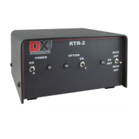
Figure A
NOTE: No reception of the RX ANT IN and receive signals through the optional modules is
possible when the keying line is not connected. Exception* - See next page.
When the RTR-2 is in the MAIN ANT transmit mode, and even when independently jumper
enabled, RTR-2 input DC voltage (+13.8 to +21 Vdc) is NOT fed onto the RX ANT IN connector
to operate Active antenna(s) – See section on Internal Jumpers.
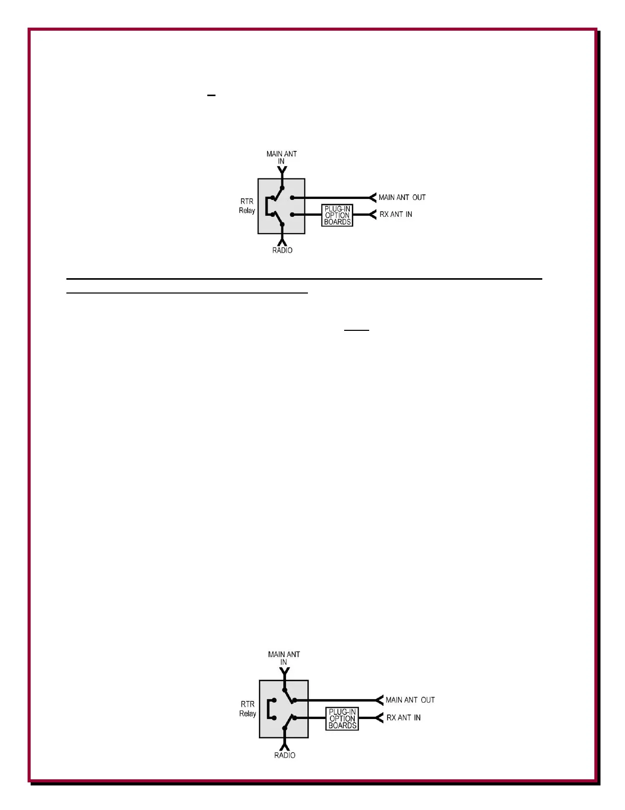
Receive Antenna Mode
In Figure B, the RTR-2 is in RX ANT receive mode, the mode LED turns to BLUE, and the
RADIO is connected to the optional modules and RX ANT IN receive signal. This receive-enabled
condition depends upon all of these items:
A coaxial cable is connected from the transceiver RF output to RADIO (or from
transceiver RX ANT IN)
The Power switch is set to On
The mode switch is set to the RX ANT position
The transceiver amp keying line is connected to RADIO PTT/RX ENABLE, shield to
transceiver chassis, center NOT grounded
The properly connected transceiver is NOT in the transmit mode
When the RTR-2 is in RX ANT mode, the receive signals from the RX ANT and optional modules
are sent to the transceiver connected to RADIO. Also in RX ANT mode, these conditions are
enabled, as shown in Fig B.
The MAIN ANT IN signal is connected to the MAIN ANT OUT.
When independently jumper enabled, RTR-2 input DC voltage (+13.8 to +21 Vdc) is fed
onto the RX ANT IN to operate Active antenna(s)
Figure B