EasyManua.ls Logo

DX Engineering EZ-Build DXE-UWA-KIT User Manual

DX Engineering EZ-Build DXE-UWA-KIT
16 pages
To Next Page IconTo Next Page
Page #1 background imageLoading...
Page #1 background image
- 1 -
EZ-Build
®
Universal Wire
Antenna Hardware Kits
DXE-UWA-KIT
DXE-UWA8X-KIT
DXE-UWA213-KIT
DXE-UWA-KIT-INS Rev 6
No Soldering
Required
DXE-UWA-KIT DXE-UWA8X-KIT
Shown with optional parts Shown with optional parts
© DX Engineering 2020
1200 Southeast Ave. - Tallmadge, OH 44278 USA
Phone: (800) 777-0703 ∙ Tech Support and International: (330) 572-3200
Fax: (330) 572-3279 ∙ E-mail: DXEngineering@DXEngineering.com
Question and Answer IconNeed help?

Do you have a question about the DX Engineering EZ-Build DXE-UWA-KIT and is the answer not in the manual?

DX Engineering EZ-Build DXE-UWA-KIT Specifications

General IconGeneral
BrandDX Engineering
ModelEZ-Build DXE-UWA-KIT
CategoryAntenna
LanguageEnglish

Summary

Introduction

Tools Required

Basic Assembly

Assembling the Center-T Support

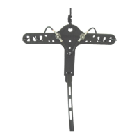
Details the initial assembly of the Center-T support common to all models.

Coaxial Cable Connections

Coaxial Cable Strain Relief Bracket Assembly

Explains how to assemble the strain relief bracket for coaxial cable connections.

Pigtail Installation

Describes the process of attaching the coaxial cable pigtail to the Center-T.

Cable Finishing and Strain Relief

Weatherproofing the Connectors

Details weatherproofing coaxial connectors using splicing tape.

P-Clamp Strain Relief Assembly

Explains the assembly of P-clamps for coaxial cable strain relief.

Wire Attachment to Insulators

Attaching Dipole Wire to the End Insulators

Describes how to weave and secure dipole wire legs through end insulators.

Feedline and Support

Attaching Rope to the End Insulators

Details securing UV protected rope to end insulators using non-slip knots.

Ladder Line Fed Antennas

Covers aspects of ladder line feed systems for antennas.

Attaching the Ladder Line Feedline to the Center-T

Describes feeding ladder line through the Center-T.

Attaching the Dipole Wire Legs to the Center-T

Explains attaching dipole wire legs to the Center-T with ring terminals.

Antenna Installation Planning

Safety Considerations

Addresses critical safety warnings, especially regarding power lines.

Mounting Considerations

Discusses factors for optimal antenna placement and height.

Support Line Usage

Antenna Configurations

Single Band Center Fed Half Wave Dipole

Explains building a single band dipole using the L=468/F formula.

Multi-Band Center Fed Shortened Dipole using Ladder Line Feedline

Details multi-band dipole construction with ladder line feed.

Sample Dipole Configurations

Presents typical applications and configurations for the kits.

Folded Dipole Element

Illustrates the setup for a folded dipole element using ladder line feed.

Dual Frequency Element

Shows a dual band dipole configuration with different cut lengths.

Ladder Line Feed

Provides notes on ladder line feed configurations.

Support and Information

Manual Updates

Information on checking for the latest manual revisions.

Technical Support

Contact details and advice for technical assistance.

Warranty

Details the product warranty terms and conditions.

Related product manuals