Inputs
DYNACO USA, INC, 10 The Leader in Door Safety & Design
5.0 Inputs
The Dynalogix II has nine inputs. Inputs are signals coming to the Dynalogix II
that gets interpreted to create a certain response. For example; a pull cord is
wired to terminal 2 on the Dynalogix II, when you pull the cord, it sends a signal
to the Dynalogix II. The Dynalogix II knows what the signal is do to the
assigned input (terminal 2) the signal is coming through on. Therefore it will
make the door go up or down. All the inputs have indicator lights and
identification. See Figure: 5.0-1.
Input 2: Typcally used for activations such as: pullcords, push buttons, photo
eye contacts etc... This input works with the MC/PB timer and can be
put in either manual or automatic operation. Refer to section: 4.1
Input 3: Typically used for activations such as: floor loops, motion sensors
and any other activations that need to be solely automatic
operations. This input works with the AC/LOOP timer. Refer to
section: 4.2
Input 4: Used for reversing edge either pneumatic (M2/M3) or Wireless
Dynaco Detector (SC+). This input works with the AC/LOOP
timer. Refer to section: 4.2
Input 5: Used for photo eye contact. This input works with the MC/PB timer
and can be put in either manual or automatic operation. Refer to
section 4.1
Input 6: Used to identify a drive error on the Variable Frequency Drive.
Note: If error light is on, check the VFD for the error code. Refer to
appendix n/a for error charts.
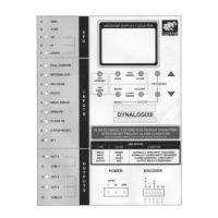
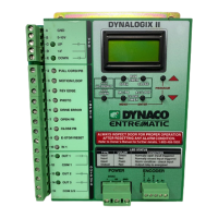
Figure 5.0-1: Nine inputs on Dynalogix II
I
N
P
U
T
S
2 PULL CORD/PB
3 MOTION/LOOP
4 REV EDGE
5 PHOTO
7 OPEN PB
9 E-STOP/RESET
8 CLOSE PB
6 DRIVE ERROR
10 IN 1
Nine inputs with
identification
and indicator
Lights
 Loading...