EasyManua.ls Logo

DYNACO Dynalogix II - User Manual

DYNACO Dynalogix II
12 pages
To Next Page IconTo Next Page
Loading...
DYNACO USA, INC, The Leader in Door Safety & Design
TECHNICAL MANUAL SUPPLEMENT
DYNALOGIXII
ALWAYS INSPECT DOORS FOR PROPER OPERATION
AFTER RESETTING ANY ALARM CONDITION
REFER TO OWNERS MANUAL FOR FURTHER DETAILS. 1-800-459-1930
LED STATUS
TYPE COLOR CONDITION
INPUT
INPUT
INPUT
OUTPUT
GREEN
RED
FLASH
RED
NORMALLY OPEN INPUT TRIGGERED
NORMALLY CLOSED INPUT TRIGGERED
ALARM CONDITION - CHECK INPUT
OUTPUT RELAY IS ENERGIZED
S
H
L
D
W
H
T
B
L
K
R
E
D
G
R
N
S
H
L
D
+
12
G
N
D
A- A+
1 X2 GND
24VAC
POWER ENCODER
V
F
D
E DOWN
D +V
C UP
B 0-10V
A GND
O
U
T
P
U
T
S
11 OUT 1
12 COM 1
13 OUT 2
14 OUT 3
15 COM 2/3
MESSAGE DISPLAY / COUNTER
JOG
UP/RESET
JOG
DOWN
OPEN CLOSE
MC/PB AC/LOOP
PROGRAM
CLOSE
TIMERS
RUN
TIMERS
ENTER
MENU
I
N
P
U
T
S
2 PULL CORD/PB
3 MOTION/LOOP
4 REV EDGE
5 PHOTO
7 OPEN PB
9 E-STOP/RESET
8 CLOSE PB
6 DRIVE ERROR
10 IN 1
Question and Answer IconNeed help?

Do you have a question about the DYNACO Dynalogix II and is the answer not in the manual?

DYNACO Dynalogix II Specifications

General IconGeneral
BrandDYNACO
ModelDynalogix II
CategoryControl Panel
LanguageEnglish

Summary

Message Display and Cycle Counter Readings

Display Readings and Actions

Translates display readings like Ready, Drive Error, Rev-Edge Tripped, timers, SET LIMITS, and ENCODER COM_LOSS with corresponding actions.

Setting Door Limits

Initial Power-Up Limit Setup

Procedure to set initial door limits on power-up, including program mode entry and button operations.

Setting;Adjusting Limits After Initial Power Up

Guidance on adjusting limits after the initial setup, recommending reference to the initial setup section.

Optional Dual Height Limit Configuration

Instructions for configuring a second height limit for doors with the dual height option.

Setting Open and Close Run Timers

Open Run Timer Adjustment

Procedure for setting the Open Run Timer duration to prevent continuous door operation.

Close Run Timer Adjustment

Procedure for setting the Close Run Timer duration as a failsafe.

Manual and Automatic Close Timers

MC;PB Timer Setting

Configuration for the MC/PB timer, which can function in manual or automatic modes.

AC;LOOP Timer Setting

Configuration for the AC/LOOP timer, typically used for motion sensors and loops.

Inputs Overview and Functionality

Dynalogix II Input Terminals

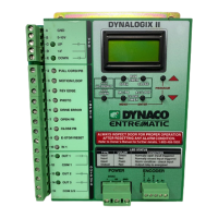
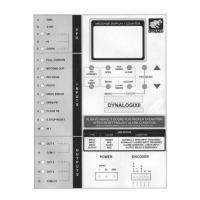
Description of the nine inputs on the Dynalogix II, their identification, and indicator lights.

Input Terminal Descriptions

Details on the typical uses for Input 2 (MC/PB Timer), Input 3 (AC/LOOP Timer), Input 4 (Reversing Edge), Input 5 (Photo Eye), and Input 6 (Drive Error).

Input Wiring and Terminal Functions

Explanation of how inputs like pull cords, sensors, and emergency stops are wired to specific terminals.

Related product manuals