7
2. Camera Cabling
Please follow the instructions below to complete IP Camera connection.
2.1 Connect Power
Please refer to Section: Connectors. Alternatively, connect the Ethernet cable to
the camera’s PoE port and plug the other end of the cable into a PoE switch.
NOTE: If using PoE, make sure Power Sourcing Equipment (PSE) is in
use in the network.
2.2 Connect Ethernet Cable
Use of Category 5 Ethernet cable is recommended for network connection; to
have best transmission quality, cable length shall not exceed 100 meters.
Connect one end of the Ethernet cable to the RJ-45 connector of the IP Camera,
and the other end of the cable to the network switch or PC.
NOTE: In some cases, you may need use an Ethernet crossover cable
when connecting the IP Camera directly to the PC.
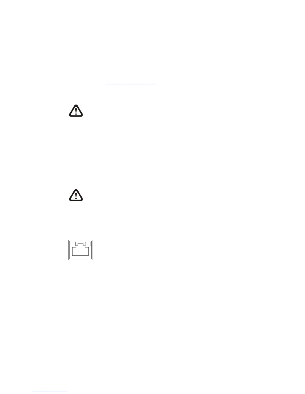
Check the status of the link indicator and activity indicator LEDs; if the LEDs are
unlit, please check LAN connection.
Green Link Light indicates good network connection.
Orange Activity Light flashes for network activity indication.
2.3 Connect Alarm I/O
The camera equips one alarm input and one relay output for alarm application.
Please refer to the label on the alarm terminal block and connect the alarm
wiring accordingly.