15
16
13. POWER SUPPLY
CONNECTION
NOTE: The battery is disconnected for
shipment to prevent the battery from
draining.
• Securely plug the battery connector into
the control module connector.
Control
Module
Connector
Battery
Connector
Battery
Cover Cap
Marks under End Caps
Top LED Lamp
Concave Point
Convex Point
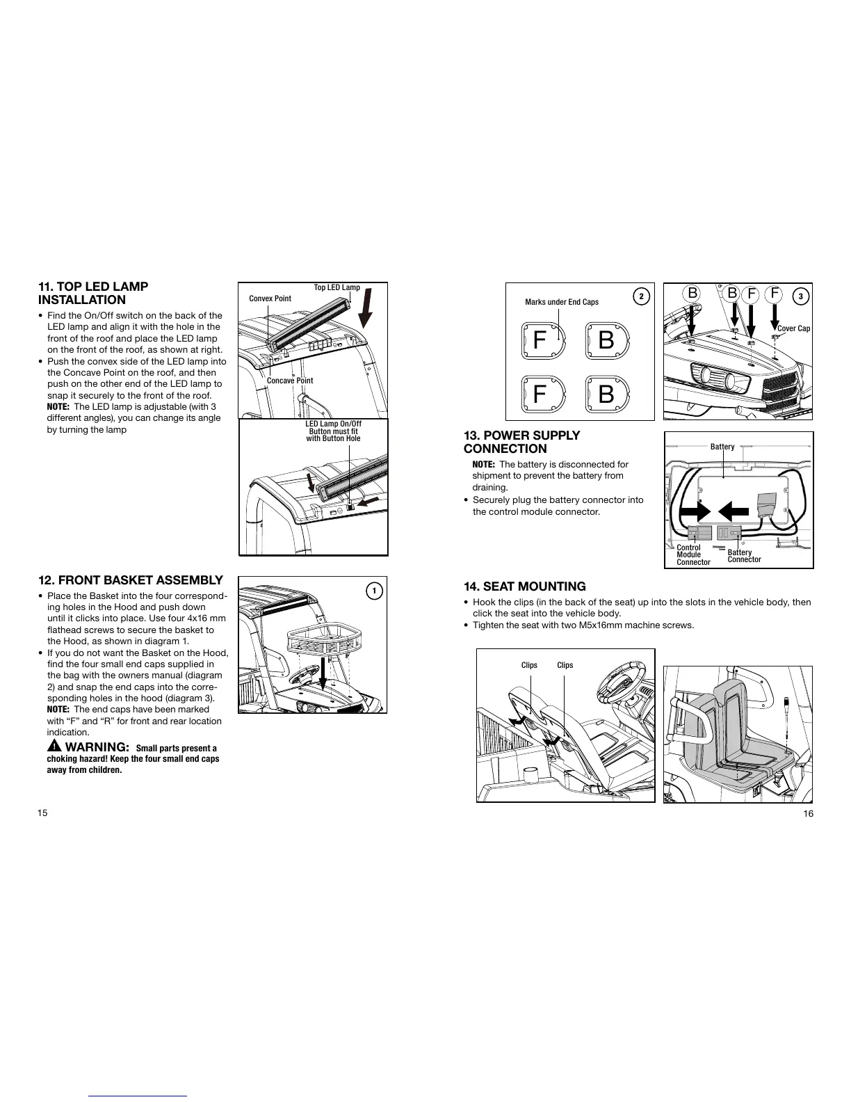
11. TOP LED LAMP
INSTALLATION
• Find the On/Off switch on the back of the
LED lamp and align it with the hole in the
front of the roof and place the LED lamp
on the front of the roof, as shown at right.
• Push the convex side of the LED lamp into
the Concave Point on the roof, and then
push on the other end of the LED lamp to
snap it securely to the front of the roof.
NOTE: The LED lamp is adjustable (with 3
different angles), you can change its angle
by turning the lamp
12. FRONT BASKET ASSEMBLY
• Place the Basket into the four correspond-
ing holes in the Hood and push down
until it clicks into place. Use four 4x16 mm
flathead screws to secure the basket to
the Hood, as shown in diagram 1.
• If you do not want the Basket on the Hood,
find the four small end caps supplied in
the bag with the owners manual (diagram
2) and snap the end caps into the corre-
sponding holes in the hood (diagram 3).
NOTE: The end caps have been marked
with “F” and “R” for front and rear location
indication.
WARNING: Small parts present a
choking hazard! Keep the four small end caps
away from children.
F
F
BB
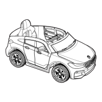
14. SEAT MOUNTING
• Hook the clips (in the back of the seat) up into the slots in the vehicle body, then
click the seat into the vehicle body.
• Tighten the seat with two M5x16mm machine screws.
ClipsClips
1
2 3
LED Lamp On/Off
Button must fit
with Button Hole
F B
BF