Do you have a question about the Dynalco SST2000A and is the answer not in the manual?
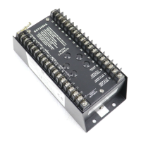
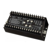
Explains the Dynalco SST-2000A/H series as a speed switch and transmitter for alarm and control applications.
Lists the different SST-2000 series models (A and H) and their features like number of set points and certifications.
Details the key features of the SST-2000A/H, including signal sources, input frequency, alarm set points, outputs, and power.
Provides detailed electrical and environmental specifications for the SST-2000A/H, including input, output, and stability.
Describes the relay logic, contact ratings for A and H series, alarm set points, hysteresis, and isolation transformer options.
Outlines available options for enclosures, open pickup, pneumatic trip, underspeed logic, and expanded scale input.
Instructions on how the SST-2000A/H is installed using standard hand tools and practices in a panel or enclosure.
Details internal commons, isolation considerations, and warnings for DC-powered units regarding signal input and output commonality.
Guides on connecting signal sources, specifically a PG-278 Pulser, to the SST-2000A/H's input terminals.
Explains how the SST-2000A/H's repeater output can be used to power external frequency instruments like tachometers.
Describes connecting DPM-105 meters to the SST-2000A/H's 0-1 mA meter output for external speed indication.
Details powering zero velocity pickups and digital indicators using the SST-2000A/H's regulated 14 Vdc supply.
Provides instructions and warnings for driving an SPV-200 solenoid pneumatic valve using the SST-2000A/H's relay contacts with current limiting resistors.
Explains how to access and interpret the programming switch instructions located under the top plate of the SST-2000A/H.
Guides on adjusting the SST-2000A/H's full-scale input frequency range using DIP switch settings and calibration procedures.
Step-by-step instructions for calibrating the SST-2000A/H after changing the full-scale frequency range or set points.
Details the procedure for calibrating the 4-20 mA proportional output or changing it to 0-5 Vdc or 0-10 Vdc.
Explains how to use DIP switches B and C to program relay set points, logic (energize/de-energize), latching, and output types.
Covers desensitizing standard inputs and contact closure inputs by adjusting the signal sensitivity potentiometer or using jumpers.
Defines response time and explains standard response times, noting field modification is not recommended.
Provides methods to adjust individual set points using signal generators and either listening for relay clicks or using an ohmmeter.
Explains how to view and adjust set point values without running the engine by using jumpers and a 0-1 mA meter.
Details the procedure for adjusting set points using a 0-1 mA meter, jumpering terminals, and referencing the full-scale frequency.
| Model | SST2000A |
|---|---|
| Type | Transmitter |
| Power Supply | 24 VDC |
| Output Power | 1 W |
| Modulation | FSK |
| Weight | 0.5 kg |
| Temperature Range | -40°C to +85°C (-40°F to +185°F) |
| Cooling System | Natural Convection |