Installation, Operation and Service Manual LKAT
2
+24V
© 2018 DynAmp, LLC Page 22
046404 E
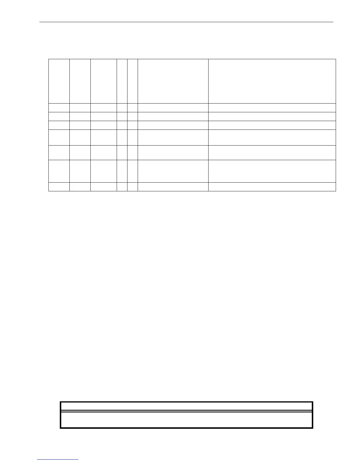
Table 5.1
Troubleshooting an Accuracy Diagnostics Fault Indication
Main
Green LED
Main
Red LED
Contact
P3-3 to P3-5
BUS ON
BUS OFF
Possible problem
Action / Check
Verify input power connection
Verify DC power on main PCB
OFF ON Closed X X
Verify head interconnections at Metering
Unit
OFF ON Closed X Head imbalance
Adjust position of head for green ON, red
OFF
OFF ON Closed X X
Measuring Head
malfunction
Measure head input signals at zero bus
current; output should be < 5mVdc;
substitute known good Measuring Head
5.7 SYSTEM CALIBRATION OVERVIEW
DynAmp does not specify exact required intervals of calibration for its products.
The end user of the product is responsible for identifying the appropriate interval between
calibrations. The intervals should be determined based on the following factors:
• Requirements of a Quality Management System
• Accuracy and permissible limits of errors
• Purpose and usage
• Experience with similar products
• Manufacturer’s recommendations
• Stability of the product
• Past history
• Other characteristics of the product
Reference: "ISO/IEC 17025:2017, General requirements for the competence of testing and
calibration laboratories" and Laboratory Accreditation Bureau "Guidance for Documenting and
Implementing ISO/IEC 17025:2005 and Laboratory Guidance."
As a guideline, DynAmp recommends a 24-month interval of calibration for all permanently
installed products and a 12-month interval of calibration for all products used in portable
applications.
Calibration may be performed as:
• Field Calibration (On Process Bus)
• Field Calibration (On Test Bus)
• Factory Calibration
DynAmp, LLC assumes no responsibility for the accuracy of LKAT
2
Systems calibrated
by any person other than a DynAmp, LLC Technician.