Do you have a question about the DYNATEK DSM-2 and is the answer not in the manual?
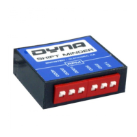
Explains the purpose, versions (DSM-2 vs DSM-4), and RPM ranges of the Dyna Shift Minder system.
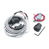
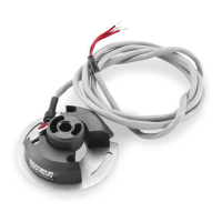
Details mounting the shift light, wiring power/ground, and connecting to coils or Tach signal.
Explains how to set the Shift Light activation RPM for DSM-4 models using switches.
Details setting the Shift Light activation RPM for DSM-2 models using switches.
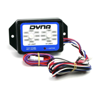
Explains RPM setting for high-RPM versions of DSM-2H and DSM-4H models.
Lists the RPM values added by each of the six switches for all models.
Specific wiring instructions for using the Shift Minder with Datalog (DCPU-1, DCPU-1CS).
Describes the function of the bulb test feature and how it works.
Provides guidance on common issues and solutions for the Shift Minder.
Details the wiring connection for the clutch switch in the auto shift configuration.
Details the wiring connection for the air kill switch in the auto shift configuration.
Warns against interrupting power to the shift minder, coils, or ignition during a shift.
Explains how to adjust kill time by modifying the air bleed or air line lengths.
Critical safety warning about the brown wire (+12 volt output) and preventing shorts.
Instructions on how to disable the bulb test feature by cutting a green wire loop.
| Brand | DYNATEK |
|---|---|
| Model | DSM-2 |
| Category | Accessories |
| Language | English |