HIGH VOLT INSTRUCTIONS
DYNATRON® 25 SERIES™ | OPERATOR’S MANUAL 40
High Volt
Instructions
High Volt electrical stimulation is a pulsed DC current with pulse durations in the microsecond range and pulse rates
ranging from 1 to 200 Hz, with peak amplitude of up to 500 Volts. e Dynatron 125 devices deliver High Volt utilizing a
twin-peak monophasic waveform.
High Volt treatments are delivered using electrodes. e device provides a dedicated channel for High Volt electrodes
treatment (HV). During High Volt treatments, the Dynatron 125 device’s other output channels (1-2-3-4) remain available
for other simultaneously stim treatments.
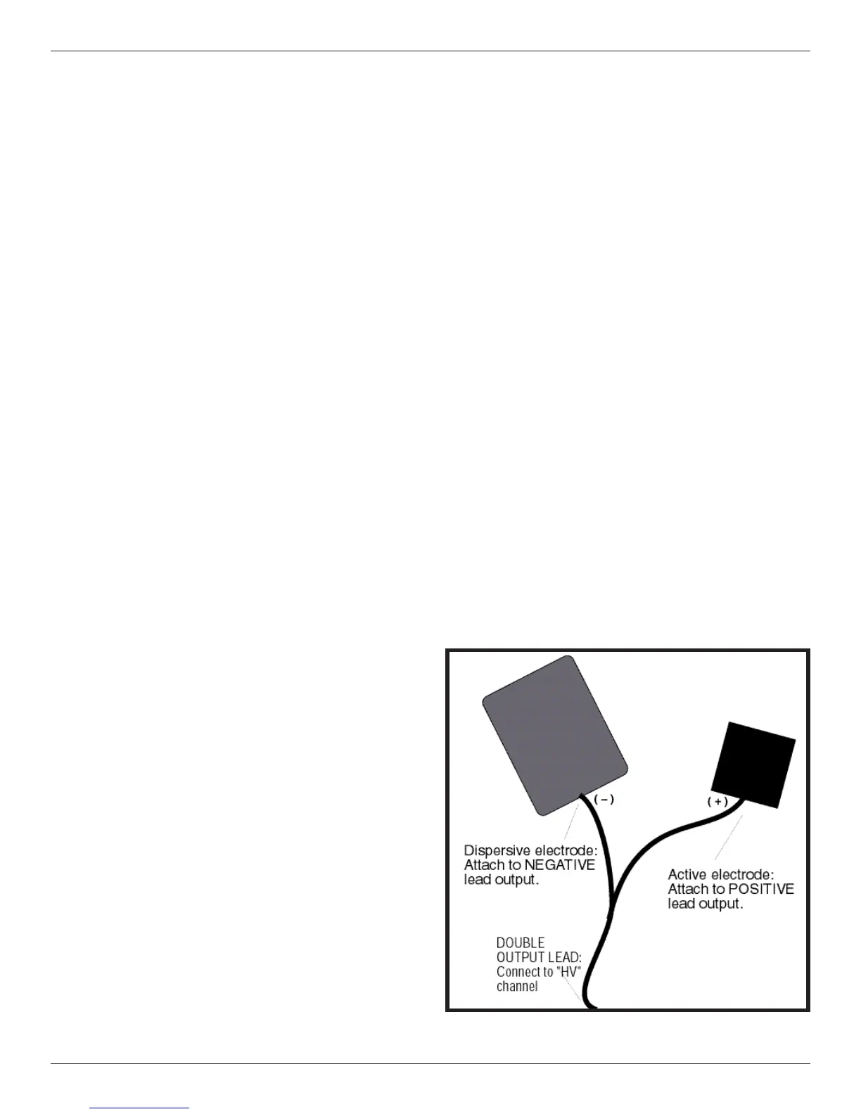
High Volt Electrode Setup
is treatment setup utilizes a standard lead wire with
two electrodes; an active and a dispersive electrode.
e size of the dispersive electrode is recommended
to be double the area of the active electrode. If desired,
the active output of the lead wire may be bifurcated by
using an optional bifurcated extension (Part no. 7B0077)
to attach additional active electrodes. However, the
combined total area of the active electrodes should be no
more than half the area of the single dispersive (passive)
electrode, as illustrated.
It is best to use a lead that is marked to show polarity. e
active electrode is connected to the positive output. e
dispersive electrode is connected to the output end that
is marked “HV Dispersive” (-). If desired, a bifurcated
lead extension may be attached to the positive (HV
Active) end of the lead wire, allowing two active
electrodes to be used. In this case, be sure the dispersive
High Volt Electrode Setup