LV-Link A User Manual
©Dyness reserves the copyright of this document.
Note:
1. For more ADD Settings
,
please refer to P7 “DIP switch definition and description”
2. After the whole system connection, set the master DIP mode according to the inverter
model firstly, then start the battery.
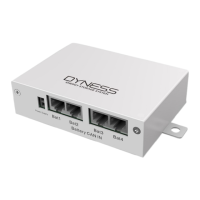
3. The BAT-INV comms cable is from inverter comm port to LV-Link Inverter CAN port,
BAT-BAT comms cable is from BAT1 CAN IN to LV-Link BAT1 CAN,BAT2 CAN IN to LV-
Link BAT2 CAN
4.The limited continuous current for each pair of power cable is 120A. Please add power
cable according to the proportion if the max working current of the inverter is more
than 120A.
Register on the website after installation
After the battery system installation is completed and the running is normal, you need to
log in to the DYNESS official website to register the product installation and use
information to make the product warranty effective. Please follow the instructions on the
website to register.
http://www.dyness.com/ Service Sign Up
 Loading...