LV-Link A User Manual
©Dyness reserves the copyright of this document.
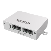
Table 2-3 Interface Definition
Master communication protocol and baud rate selection.
Table 2-1 for details.
The green light is always on for normal.
The red light is always on or flashing to indicate an alarm.
The flashing yellow light indicates communication
disconnection between the battery and the LV-Link A.
If the green indicator blinks, the DIP Switch of LV-Link A is
not turned.
Communicates with the COM port of the inverter
Communicates with the COM port of the inverter
The interface is used to power the LV-Link A
Communicates with the COM port of the Battery1
Communicates with the COM port of the Battery2
Table 2-4 DIP switch definition and description
DIP switch position (master communication protocol and baud rate selection)
Define different protocols
;
Distinguish between master and slave
When the batteries are connected in parallel, the master communicates with the
slaves through the CAN interface. LV-Link summarizes the information of the entire
battery system and communicates with the inverter through CAN or 485.
If the master is the LV-Link with DIP switch:
1. The communication cable from LV-Link CAN IN to the inverter comm port
should be the correct one.