EasyManua.ls Logo

Dyness Tower T Series - User Manual

Dyness Tower T Series
8 pages
Print Icon
To Next Page IconTo Next Page
Loading...
Dyness Battery System
Tower T Series-T7/T10/T14/T17/T21
QUICK INSTALLATION GUIDE
V1.0
File version-20221018-V1-EN information might be subject to change without notice during product improving.
Question and Answer IconNeed help?

Do you have a question about the Dyness Tower T Series and is the answer not in the manual?

Summary

Target Group

Installation Environment and Tools

Installation Environment Requirements

Specifies environmental conditions like temperature, humidity, and protection against elements.

Tools Required

Lists essential tools for installation, including wire clamp and screwdriver.

Product Components and Overview

Packing List

Details the items included in the package, such as cables and connectors.

Overall Structure

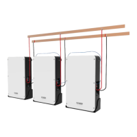
Illustrates the system architecture and module capacity limits.

Installation Steps

Unpack and Prepare Components

Instructions for unpacking the BDU and Base, and separating them.

Balance and Secure Modules

Guidance on balancing the system and stacking/locking modules securely.

Electrical Connections and Grounding

Steps for connecting communication and power cables and establishing earth connection.

System Power On and Parallel Operation

Procedures for turning on the battery system and setting up parallel configurations.

Inverter Connectivity and Expansion

KOSTAL Plenticore Plus Connection

Details the communication cable connection for KOSTAL Plenticore Plus inverter.

Ingeteam Inverter Connections

Guides for connecting Ingeteam SUN STORAGE1 PLAY TL M and 100TL inverters.

Goodwe ET Inverter Connection

Instructions for connecting the Goodwe ET inverter using a standard communication cable.

Solis RHI Series Hybrid Inverter Connection

Guidance on using the standard network cable for Solis RHI Series Hybrid Inverter.

Module Expansion

Steps for adding modules to the system, ensuring proper charge and capacity.

Overview

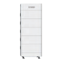
The Dyness Battery System, specifically the Tower T Series (T7/T10/T14/T17/T21), is an energy storage solution designed for residential and commercial applications. This Quick Installation Guide outlines the setup and operation of these battery systems, emphasizing safety, proper installation, and system expansion.

Function Description

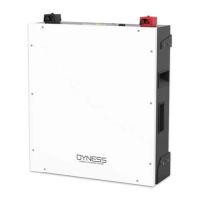
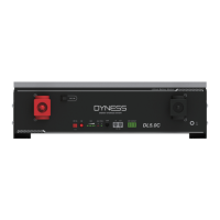
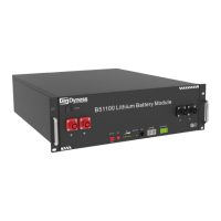
The Dyness Tower T Series batteries are designed to store electrical energy, providing a reliable power source for various applications, particularly in conjunction with inverters in on-grid systems. The system consists of a Battery Distribution Unit (BDU) and multiple HV9637 battery modules, stacked on a base. The BDU manages the battery modules, ensuring safe and efficient operation. The system supports parallel operation for increased capacity and power output, accommodating up to 12 clusters with a dedicated flow box.

Important Technical Specifications

The Tower T Series offers various capacities:

  • T7: 7.1 kWh
  • T10: 10.6 kWh
  • T14: 14.2 kWh
  • T17: 17.7 kWh
  • T21: 21.3 kWh

The system operates within a broad environmental range:

  • Operating Temperature: -10°C to +50°C
  • Relative Humidity (RH): 5% to 95%

The number of HV9637 modules used by the Tower series products is limited to 2, based on the inverter's voltage interval. The maximum number of HV9637 modules in the Tower series is 6, limited by the BDU's internal DC conversion conditions.

Communication: The system uses RJ45 communication cables for connection to inverters. Specific wiring diagrams are provided for various inverter brands:

  • Kostal Plenticore Plus: Uses pins 1.485A and 2.485B.
  • Ingeteam (INGECON SUN STORAGE1 PLAY TL M): Uses pins 4.CAN H and 5.CAN L.
  • Ingeteam (INGECON SUN STORAGE 100TL): Uses pins 4.CAN H and 5.CAN L.
  • Goodwe ET Inverter: Connects directly to the CAN port of the battery BDU, using pins 4.CAN H and 5.CAN L. The inverter version should be xxxx 22.
  • Solis RHI Series Hybrid Inverter: Uses pins 4.CAN H and 5.CAN L.

Cabling:

  • Communication Cable to Inverter: Standard, Black, L2000mm, RJ45 plug at both sides (1 PCS).
  • Communication Connector to BDU: RJ45 Waterproof connector (1 PCS).
  • Power Cable: Positive (6mm², red, 2m) and Negative (6mm², black, 2m) cables (1 PCS each).
  • Power Cable Connector: For positive and negative poles of the battery (1 PCS each).
  • OT terminal for Ground: OT4-6 (2 PCS).

Usage Features

Installation:

  • Target Group: Installation must be performed by skilled personnel recognized as trained and qualified electricians or installers with knowledge of on-grid systems, electrical device installation, and safety precautions.
  • Environment: The battery system should not be installed in direct sunlight, direct rainfall, areas with snow accumulation, or near flammable materials or walls.
  • Unpacking and Separation: The BDU and Base are separated from the HV9637 modules during unpacking.
  • Balancing: The base must be balanced on a flat surface, with a recommended distance of D1=50cm and D2=30cm for stability.
  • Stacking and Locking: Battery modules are stacked on the base, with the BDU placed on top. The circuit breaker switch of the BDU must be in the "OFF" state during assembly. Fixed bolts are tightened in turn to secure the stack.
  • Cable Connection: Communication cables are connected between the BDU and the inverter. Power cables are connected to the positive and negative poles of the battery.
  • Earth Connection: A ground wire (10±0.5mm) must be connected for safety.
  • Circuit Breaker Recommendation: It is recommended to install a circuit breaker between the battery and the inverter to prevent damage during short circuits.

System Operation:

  • Powering On:
    1. Push the circuit breaker of the BDU to the "ON" state.
    2. Turn the self-locking switch to "ON".
    3. Press and hold the "WAKE" button for 3-7 seconds. Release the button when the green light is continuously on, indicating successful battery activation.
  • Parallel System: Dyness supports up to 12 clusters for parallel operation, requiring a dedicated flow box. Single cluster installation follows the same procedure as a standalone unit.

Module Expansion:

  • Prerequisite: For module expansion, it is crucial to ensure that the added module and the expanded system both have a State of Charge (SOC) of 100%. Dealers are expected to provide 100% SOC modules.
  • Procedure (if operating by yourself):
    1. Add the module to be charged between the BDU and the Base.
    2. Charge the module with a DC power supply until the BDU cuts off, indicating 100% SOC.
  • Note: If equipment for charging is unavailable, contact the dealer to fill up the capacity of the module.

Maintenance Features

  • Firmware Updates: To ensure normal operation, the Battery-Box firmware must be updated to the latest version, and configuration completed via the Battery-Box webpage.
  • Troubleshooting: If the system is not working, ensure the system switch is off. If issues persist, repair should be initiated within one week to prevent over-discharge or other problems.
  • Storage: Batteries should not be stacked without protective packaging when storing or handling, except during installation.
  • Documentation: This Quick Installation Guide is a shortened reference. The original installation manual, available on www.eft-systems.de (Downloads), must be read and understood completely before installation.

The Dyness Battery System aims to provide reliable and scalable energy storage, backed by clear installation guidelines and essential safety measures.

Dyness Tower T Series Specifications

General IconGeneral
BrandDyness
ModelTower T Series
CategoryBattery Pack
LanguageEnglish

Related product manuals