Do you have a question about the Dyness B3 and is the answer not in the manual?
Critical safety warnings about potential hazards like explosion, electric shock, and misuse.
Important notes regarding product handling, environment, charging practices, and unauthorized maintenance.
Declaration concerning the manual's content, purpose, and copyright.
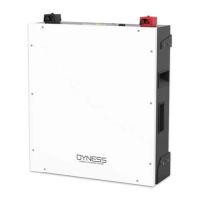
Overview of the B3 lithium iron phosphate battery energy storage system's capabilities.
Features, materials, and management capabilities of the B3 battery system.
Explanation of symbols and labels on the battery for identification and safety.
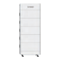
Details on the physical dimensions and weight of the B3 battery module.
Key technical parameters like voltage, capacity, power, and current ratings.
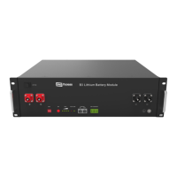
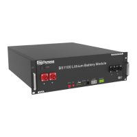
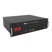
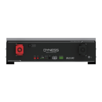
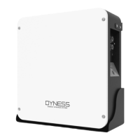
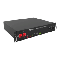
Explanation of the functions of the front panel interface ports.
Detailed descriptions of each interface port and indicator on the battery module.
Configuration of DIP switches for communication protocol and baud rate selection.
Examples of master DIP switch settings for compatibility with various inverters.
Instructions for setting DIP switches on slave battery modules for communication.
Detailed pin definition for the CAN/485 communication port.
Interpretation of LED lights for battery status, charging, and discharging.
Overview of BMS functions, including voltage, current, and temperature protection.
Details on low and over-voltage protection during charging and discharging.
Explanation of over-current protection mechanisms during charging and discharging.
Description of low and over-temperature protection during operation.
Details on short circuit protection and self-shutdown features.
Essential safety precautions and personal protective equipment needed for installation.
Specifies the ideal working environment, temperature, humidity, and location conditions.
Lists required hardware tools and procedures for technical preparation.
Procedures for verifying DC output interface compatibility and voltage range with connected equipment.
Guidelines for security measures, fire safety, and proper unpacking procedures.
Details the items in the packing list and provides coordination points for installation wiring.
Step-by-step guide for mechanical, electrical, and self-test procedures during installation.
Describes two methods for physically mounting the B3 unit using fixed racks or flexible brackets.
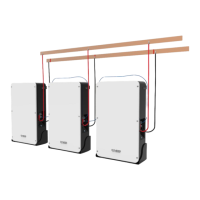
Instructions for stacking multiple B3 units using brackets and securing them.
Procedures for power cable checks, connection, and selecting an appropriate circuit breaker.
Visual guide for connecting battery modules to the inverter, including DIP settings and cable notes.
Recommended settings for Max Charging, Absorption, Float, Shut Down voltages, and current limits on the inverter.
Instructions for registering the product on the Dyness website for warranty activation.
Steps for starting the battery system after installation, including DIP switch and power button operations.
How to interpret alarm signals on the front panel and troubleshooting steps for common issues.
Troubleshooting guide for common faults, including indicator issues, no DC output, and charging problems.
Further details on power cable sparks, communication faults, and their potential causes and solutions.
The Dyness B3 is a lithium iron phosphate battery energy storage system designed to provide energy for photovoltaic power generation users through parallel combination. This product is suitable for energy storage applications with high operating temperatures, limited installation space, long power backup time, and long service life. It can store extra electricity from photovoltaic power generation systems in the daytime and supply stable power to users' equipment as power backup at nighttime or any time when needed. It improves the efficiency of photovoltaic power generation and increases electric power efficiency by peak load shifting.
To start the battery system after electrical installation, users should refer to the DIP switch description (Section 2.3.1) to prepare the battery module. Then, press the ON/OFF button to the ON position and hold the SW button for 3 seconds. After the indicator self-test, the RUN indicator will light up, and the SOC indicator will be on, indicating a 100% SOC status.
When the battery system is running, users should regularly check the battery status indicators on the front panel. If the battery status indicator continues to be red after pressing the power button, it indicates a potential issue that requires attention. In such cases, users should refer to the "Alarm description and processing" section (Section 4.2) for troubleshooting. If the failure cannot be resolved, it is recommended to contact the dealer.
To ensure proper operation, users should use a voltmeter to measure whether the voltage of the circuit breaker battery access terminal is higher than 42V and verify that the voltage polarity is consistent with the inverter input polarity. If the battery input terminal has a voltage output greater than 42V, the battery is working normally. After confirming the correct battery output voltage and polarity, the inverter should be turned on, and the circuit breaker closed. Users should then check if the indicators for the inverter and battery connection (communication indicator and battery access status indicator) are normal. If they are, the connection between the battery and the inverter is successful. If the indicator light is abnormal, users should consult the inverter manual for the cause or contact the dealer.
The battery system supports various operational modes, including charging and discharging. During charging, the battery charges until it reaches its maximum capacity or until the charge current drops below a certain threshold. During discharge, the battery supplies power to the inverter until its voltage reaches the shut-down voltage or its SOC drops to the cut-off SOC.
The system also includes various protection features to ensure safe operation. These include over-current protection, high-temperature protection, total voltage undervoltage protection, and cell voltage undervoltage protection. When any of these protection modes are activated, the system will trigger an alarm and stop the relevant operation (charging or discharging) to prevent damage to the battery.
For parallel connection, the master battery communicates with the slaves through the CAN interface, summarizing the information of the entire battery system and communicating with the inverter through CAN or 485. The communication cable from the master CAN IN to the inverter communication port should be correct. When the battery works with specific inverter brands (GOODWE, Solis, LUX, Sofar, DEYE (SUNSYNK), VICTRON, IMEON, Sungrow, SMA, RENAC, DELIOS, SAJ (CAN Comm)), users need to put the master DIP switch "#3" to the "ON" position (to the top), then turn on the batteries. If the battery communicates with other brands (Axpert-king/VMIII/MAX, Infinisolar, Growatt SPH/SPA (CAN comm), GMDE), users should turn the master DIP switch "#2" to "ON" position. For communication with Growatt SPF HVM-P/ES/WPV by RS485, users should turn the master DIP switch "#2" and "#3" to "ON". If the battery communicates with the Schneider Conext Series, users should turn the master DIP switch "#1" and "#3" to "ON". When setting the master DIP as setting 1-4, all the slaves keep the DIP 0000, no need to change. If the battery module is in communication with the ICC by 485 communication, users should turn the master DIP switch "#1" and "#4" to "ON". The DIP switch of slaves needs to be turned to the "ON" at the same time while the master is setting 5. If the energy storage system has only one B3, it is the master itself, and users should follow the above steps.
The battery system is designed for long-term reliability, but regular checks and maintenance are recommended to ensure optimal performance and longevity.
Alarm Description and Processing: When a protection mode is activated or a system failure occurs, an alarm signal will be given through the working status indicator on the front panel of the B3. The network management system can query specific alarm categories. If the battery status indicator continues to be red after pressing the power button, users should refer to the "Alarm description and processing" section. If the failure cannot be eliminated, contact the dealer promptly.
Battery Management System (BMS): The BMS continuously monitors the battery's health and protects it from various issues.
After the battery system installation is completed and running normally, users need to log in to the DYNESS official website to register the product installation and use information to make the product warranty effective. Follow the instructions on the website to register.
| Battery Type | Lithium Iron Phosphate (LiFePO4) |
|---|---|
| Nominal Voltage | 51.2 V |
| IP Rating | IP20 |
| Cycle Life | 6000 cycles at 80% DoD |
| Communication | CAN, RS485 |
| Peak Discharge Current | 100A (15s) |
| Operating Temperature Range | -20°C to 55°C |