B3 ESS Unit User Manual
©Dyness reserves the copyright of this document.
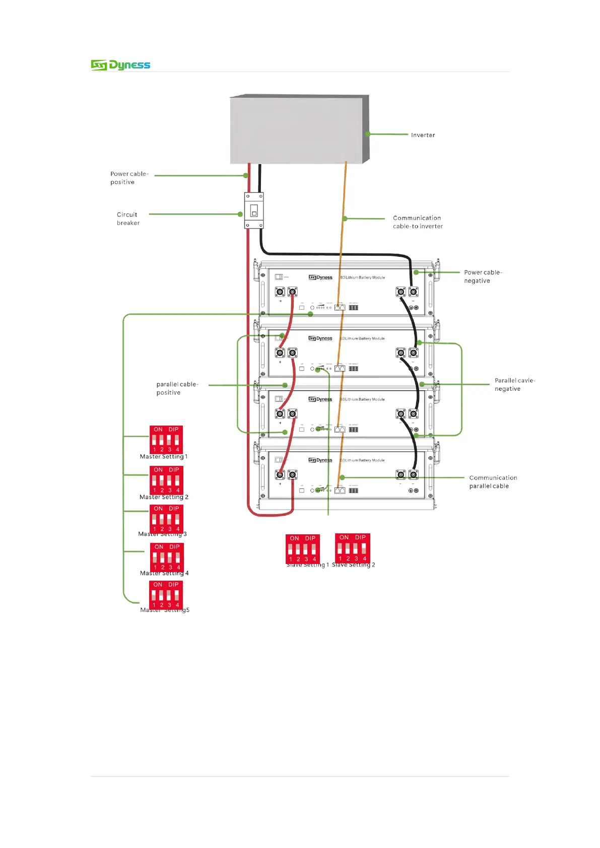
Figure 3-9
Note: 1.After the whole system connection,set the master DIP mode according to the
inverter model firstly,then start the battery.
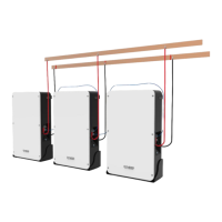
The BAT-INV comms cable is from inverter comm port to master CAN IN port,BAT-BAT
cable is from master CAN OUT to slave1 CAN IN,slave1 CAN OUT to slave2 CAN IN…
Each pair of power cable,it’s limited continuous current is 120A,so if the inverter Max.work
current more than 120A,please add power cable according to the proportion.