B3 ESS Unit User Manual
©Dyness reserves the copyright of this document.
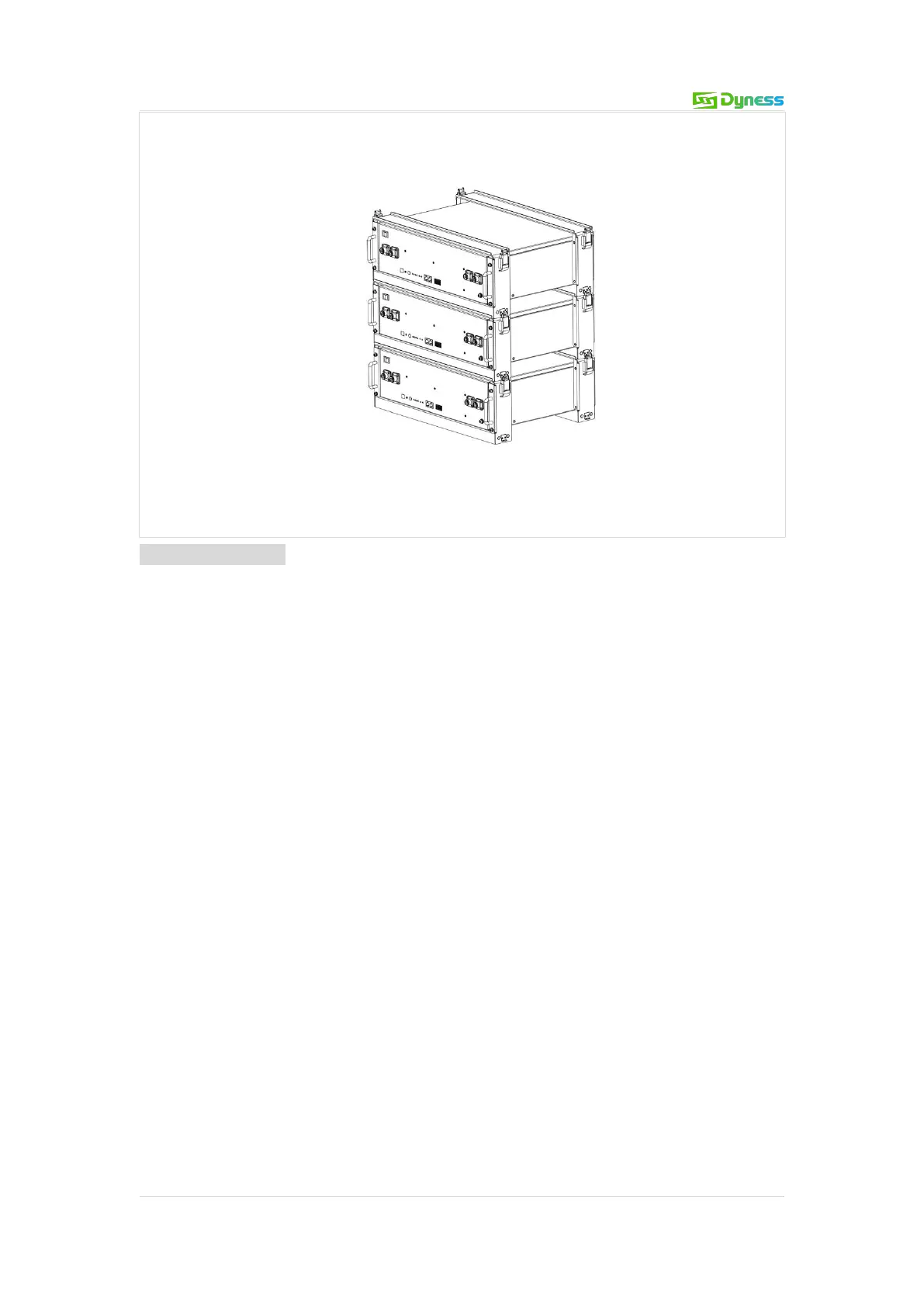
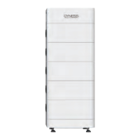
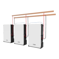
4. Stack the required number of battery and bracket combinations as described above,
and fasten the top and bottom buckles. Shown as Figure3-8.
Figure 3-8
Electrical installation
Before connecting the power cables, use multimeter to measure cable continuity, short
circuit, confirm positive and negative, and accurately mark the cable labels.
Measuring methods:
Power cable check: select the buzzer mode of multimeter and detect the both ends of
the same color cable. If the buzzer calls, it means the cable is in good condition.
Short circuit judgment: choose multimeter resistor file, probe the same end of positive
and negative pole, if the resistor shows infinity, means that the cable is available.
After visual testing of power line connection, the positive and negative poles of the
battery shall be connected respectively to the positive and negative poles of the
opposite terminal.
It is better to add a circuit breaker between the inverter and the battery system. The
selection of the circuit breaker requires:
Voltage: U>60V
Current: I =Inverter power/45V
The circuit breaker is installed between the battery module and the inverter, as shown in
Figure 3-9: