Danger to life due to high voltages!
Disconnect the inverter from all the external power sources before maintenance
Failure to observe any warnings contained in this manual may result in injury.
Hot surface! Burn danger due to hot surface that may exceed 140
o
F.
Products shall not be disposed of as household waste.
5min
Refer to the operating instructions.
Do not touch live parts for 5 minutes after disconnection from the power sources.
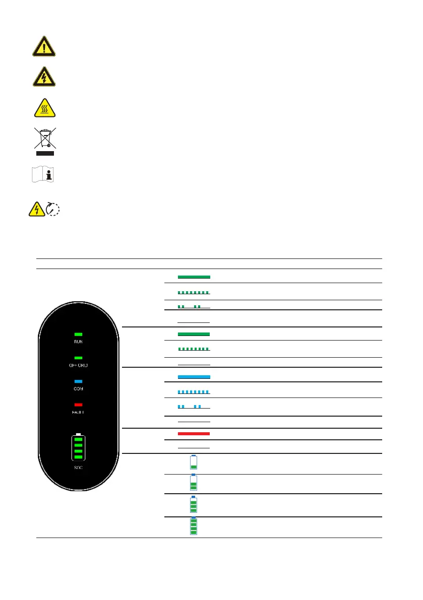
LED Indicators
LED INDICATOR LED STATUS
DEFINITION
RUN
ON = Inverter is running
Single Flash = Inverter is power on
Double Flash = Inverter is starting
OFF= Inverter is not operaring
OFF GRID
ON = Back-up is ready
Single Flash =Grid bypass mode
OFF = Back-up port no voltage
COM
ON = BMS and meter communication ok
Single Flash = Meter communication ok, BMS communication
fail
Double Flash = BMS communication ok, Meter
communication fail
OFF = BMS and Meter communication fail
FAULT
ON =Error Occured
OFF = No Errors
SOC
4th LED Blinks = 0%≤SOC≤25%
3rd LED Blinks = 25%<SOC≤50%
2rd LED Blinks = 50%<SOC≤75%
1rd LED Blinks = 75%<SOC≤100%
The LED indicator on the front of the inverter can indicate the current working state of the inverter.
2
 Loading...