18
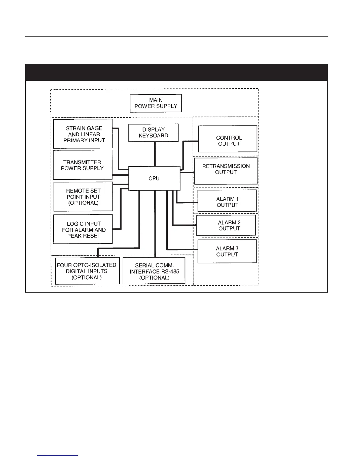
3.2 ATC770 BLOCK DIAGRAM
Fig. 1 ATC770 Electronics Layout Block Diagram
NOTE: Dashed Line represents insulation boundary.
4. MOUNTING AND WIRING
Please refer to Figure 2 for cutout dimensions and clearance requirements. Locate the two mounting
brackets packed with the instrument and have them available.
1. Remove instrument from case. To accomplish this, spread the two locking tabs located on either
side of the case . The instrument will move forward past the locked position. Grasp the bezel
and slide the instrument from the case. Depending on the options chosen, you may find that
one or two boards appear to be loosely mounted. This patent-pending design allows the
instrument to be removed from the case without having to overcome the friction of all terminals
on all boards at one time. Initially the CPU board and alarm board will be released, followed by
the I/O and digital communication boards.