54
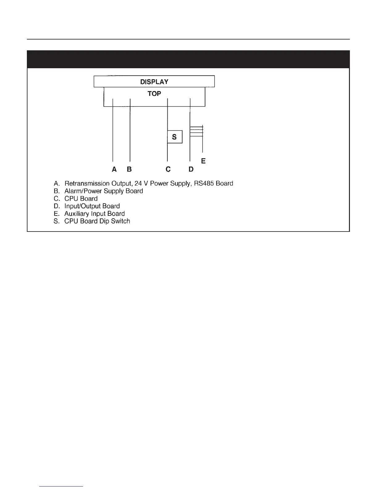
Fig. 13 ATC770 Board Location
CPU BOARD DIP SWITCH POSITIONS
Operating Mode SW1 OFF SW2 OFF
Calibration Mode SW1 ON SW2 OFF
Factory Mode SW1 OFF SW2 ON
Security Mode SW1 ON SW2 ON
8.2 GENERAL CALIBRATION PROCEDURE
1. Set the DIP switches to calibration mode as shown above. The upper display should show
CAL
while the lower display shows
ATC
.
2. Use the ▼ or ▲ keys to show the following functions:
•Firmware revision
• Zero input counts (ZERO)
• Pressure input counts (STR)
• Reference junction counts (RJ)
• Remote set point, linear temperature input and line resistance for RTD input (RSP.RL)
•Thermocouple and RTD input (TC.RTD)
• Digital inputs status (DIG.IN)
•Maximum Power Consumption (normally Blank)
• All LED’s lighted.