SkyView
HDX System Equipment Installation Record, Revision A
Three-Point Reference System
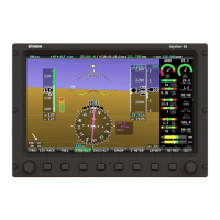
The SkyView HDX system equipment installed in this airplane can be located using the Three-
Point Reference System adopted by the manufacturer of the airplane. Figure 1 is an example of
the Three-Point Reference System as applied to a common general aviation airplane.
Figure 1: Typical Three-Point Reference System Datum Locations
Station Line Locations
Stations (STA) designate locations along the length of the aircraft in inches, starting from nose
to tail. Station 0 (see Figure 2) is often located in front of the airplane, but it can also be located
on a prominent feature of the airplane like the firewall. Station 0 is referred to as the datum.
Airplane manufacturers tend to identify prominent structures like a frame with its station location
in inches. For example, Frame 210.10 would be located 210.10 inches aft of the datum (STA0).
Figure 2: Example of Station Lines


 To Next Page