55
12. 水道管カバーを取り付けます。
図に示すように(同梱品の2本のねじを使用して)水道管カバーをバッ
クプ レ ートに固 定しま す。
13. モーターバケットを装着します。
1. モーターバケットを電子部品カバーの上部に取り付けます。図に示
すように 定位 置 でカ チッと 音 が するま で 下 方 向 にゆっくり動 かしま す。
しっかりと 押し入れます。
2. 本ユニットが正しい動作をするかテストします。
3. モーターバケットを取り外すには、底部のリリースキャッチに押し入
れて 持 ち上 げ ま す。
モーターバケットをバックプレートに固定します(オプション)。
1. フィルターを取り外すには、ドライバーをゆっくりと回して、図に示
すようにフィル ター の タ ブ を 解 放しま す。
2. 同梱品の安全ねじを使ってモーターバケットをバックプレートに固
定します。
3. フィルターを固定します。.
US/CA
1. Position.
WARNING
Use caution when unpacking the components. There may be sharp
edges/corners which may cut or cause harm.
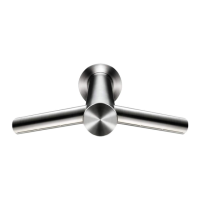
1. Position the tap and centre over the sink as illustrated. Mark the
position.
2. Cut a hole to the correct size of 35mm in the work surface.
3. Ensure the required electrical and mixed feed water supplies are
available for later connection.
Note: The sinks should not be fitted with plugs.
2. Install tap.
1. Slide the larger rubber seal onto the tap stem.
2. Feed the tap stem and the attached water tube and communications
cable through the hole in the work surface.
3. Slide the smaller rubber seal on to the underside of the tap stem.
4. Screw the tap nut onto the tap stem. Secure it tightly so it holds the
tap in place against the work surface.
5. Remove the cleaning cap on the sensor.
Store safely, as it is required during cleaning.
3. Install hose.
1. Slide the hose up over the water tube and communications cable.
2. Feed the water tube through the appropriate exit hole in the hose
duct as shown. Use pliers to gently pull the water tube through as far
as the solid white line.
3. Feed the communications cable through the appropriate exit
hole as shown. Do not use pliers as this may damage the electrical
connections. Ensure the grommet on the cable fits tightly into the hose
duct so that it is airtight.
4. Screw the upper hose collar onto the tap stem so that it is hand tight.
5. Remove the electrics cover and the water pipe cover using a
T15Torx screwdriver (see steps 9, 12)
4. Select backplate position.
1. The backplate can be positioned in one of three ways: vertical,
or 90° horizontal left or right. Clearance from the floor should be a
100mm minimum.
2. Position the backplate so the hose can reach it.
3. Mark the location of the backplate on the wall with a pencil. Use the
backplate to mark the locations for the (4) fixing points.
CAUTION: Do not use the backplate as a guide when drilling. Ensure
no pipe work (gas, water, air) or electrical cables, wires or ductwork
are located directly behind the drilling/mounting area.
4. Drill holes in the wall.
Cable entry
Cable entry can be either from the base or from the wall directly into
the back of the unit via the rear cable entry point. Decide which before
you start.
If choosing the cable entry option through the base, use pliers to
carefully nip out the premarked break-out panel on the base of the
backplate. File the edges of the break-out section smooth.
5. Secure the backplate to wall.
Note: If cable entry is to be directly into the backplate from the wall,
pull through the electrical cable before securing the backplate to the
wall.
1. Secure the backplate to the wall using the appropriate fixings.
Do not use countersunk screws.
2. Do not use sealant when fixing the unit to the wall.
6. Connect communications cable and hose.
1. Plug the communications cable in the hose into the connector in the
backplate as shown.
Check the orientation of the connector – the two tabs must be lined up.
Ensure the cable is correctly routed in the channel in the backplate.
2. Clip the hose into the backplate.
7. Connect water tube.
1. Cut the water tube to size at the dotted white line.
2. Slide the fixing clip (supplied) onto the water tube.
3. Connect the water tube onto the water connection on the backplate
as shown.
4. Secure with the fixing clip.
8. Wire main electrical power cable.
WARNING: Risk of electric shock!
1. Connect the electricity supply using approved flexible or solid
conduit and electrical fittings.
Ensure that the flexible or solid conduit and wires are long enough to
connect to the backplate and the terminal block. Tighten the cable
gland.
2. Secure the live and neutral wires into the corresponding terminal
block locations. Verify the connections are correct before proceeding.
9. Install electrics cover.
• Electrics cover fixing locations 6x fixings included Secure the
electrics cover as illustrated with the (6) fixings. Ensure no wires are
trapped when securing the cover.
10. Connect the mixed water supply.
1. Connect the isolated mixed water supply to the connection on the
backplate.
2. Turn on the water.
11. Check for leaks.
1. Switch on.
2. Place hand under sensor on tap to activate water flow.
3. Inspect for leaks at the main water supply inlet and the water tube
connection to the tap.
12. Install water pipe cover.
Secure the water pipe cover on to the backplate as shown (using the
two screws provided).
13. Attach motor bucket.
1. Hook the motor bucket to the top of the electrics cover. Swing it
downwards so it clicks into place as shown. Push in securely.
2. Test the unit for correct operation.
3. To remove the motor bucket, press in the release catch at the
bottom and lift up.
Securing motor bucket to backplate (optional).
1. To remove the filter, gently use a screwdriver to release the tab on
the filter as shown.
2. Secure the motor bucket to the backplate using the security screw
supplied.
3. Connect filter.
USES
1. Colóquela en la posición deseada.
ADVERTENCIA
Sea cuidadoso al desembalar los componentes. Es posible que tengan
bordes o esquinas filosas que pueden provocar cortes u otros daños.
1. Coloque la toma y dispóngala en el centro encima del fregadero,
como se muestra en la ilustración. Marque la ubicación.
2. Corte un orificio del tamaño correcto (1,38 pulgadas) en la
superficie de trabajo.
3. Asegúrese de que estén disponibles los suministros de agua de
alimentación mixta y de corriente eléctrica para conectarlos más
adelante.
Nota: los fregaderos no deben tener enchufes.
 Loading...