ADJUSTMENTS
LED’s have 6 different signals. The definitions:
• ON
• OFF
• Slow blink: 0.75 sec ON - 0.75 sec OFF
• Fast blink: 0.10 sec ON - 0.40 sec OFF
• Change blink: 0.75 sec ON - 0.25 sec OFF (it seen when adjusting service setting parameters)
• Update blink: 0.15 sec ON - 0.15 sec OFF (it seen when adjusting service setting parameters)
Service Level (read-out modes, setting mode and fault history)
- In case of normal operation in DHW or CH mode and no error conditions it is always possible to
enter the service level by pressing the service push-button PB3. If there was an error condition,
service level can be entered after normal operating conditions are reached again.
- Service level consists of 4 level (L1, L2, L3, L4).
Level 1 (L1) and Level (L2) are read-out modes to read some boiler parameters
Level 3 (L3) is setting mode to set some boiler parameters.
Level 4 (L4) is fault history and permits to read the last 8 error codes.
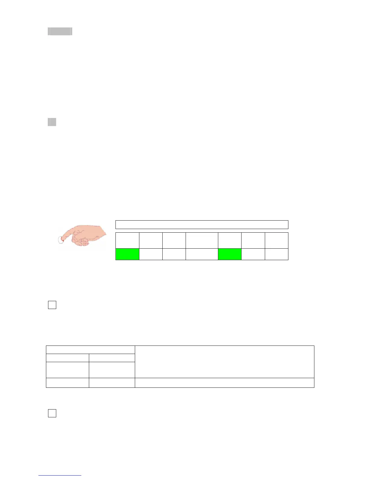
- While in service level. LED L7 is on (fig. 20)
Service level is active.
L1 L2 L3
7 segment
display
L7 L8 L9
ON OFF
ON OFF OFF
fig. 20
- All read-out and setting modes including fault history display is disappeared and deactivated after
2 minutes if nothing done.
Level 1 (read-out mode)
1
- Press PB3 service push-button once, and see “ L 1 ” on the 7 segment display.
- Press PB2 user push-button once. Anti-cycling time will appear on the 7 segment display.
Table 21
7 segment display
1st 2nd
after pressing
PB3 once
after pressing
PB2 once
Description
L 1
88
Anti-cycling time
- After pressing PB2 one more time, the display goes back to “ L 1 ”.
Level 2 (read-out mode)
2
- Press PB3 service push-button twice, and see “ L 2 ” on the 7 segment display.
- Press PB2 user push-button progressively to read some parameters detailed in Table 22.
34