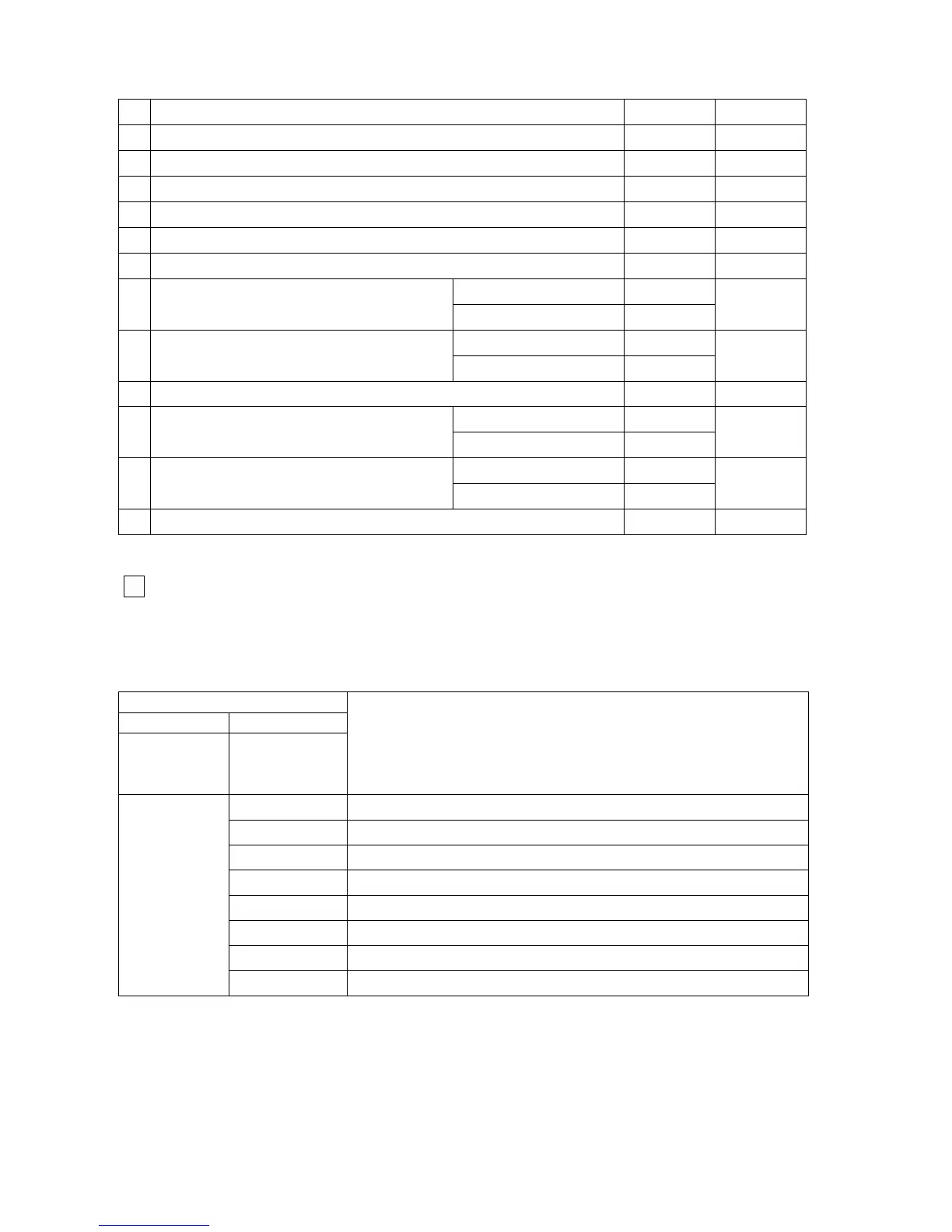
Table 24 Parameters
No Definition Range Default
1
CH water SET temperature range (
o
C)
40 – 80 -
2
DHW SET temperature range (
o
C)
35 – 60 -
3 Minimum power (%) 0 – 30 3
4 Maximum power (%) 80 – 100 100
5 Ignition power (%) 20 – 70 50
6 Anti-cycling time (min) 0 – 15 3
F1: ON=3 OFF= 2,5 -
7 DHW ON-OFF flow rate (ltr/min)
F2: ON=3,5 OFF= 3 -
F1
d1: 0 -
8 DHW delay time (sec)
d2: 1 -
d1
9 OTC curve foot point (
o
C) 10 - 50 25
o1: inactive -
10
Outside temperature limiting
set point
o2: active -
o1
P1: Mode 1 -
11 Pump control mode
P2: Mode 2
P2
12
Modulation start point ∆T (F/R), if return sensor existing
(
o
C)
10 - 30 20
Level 4 (fault history)
3
- Press PB3 service push-button 4 times, and see “ L 4 ” on the 7 segment display.
- Press PB2 user push-button progressively to reach the last 8 error codes
Table 25
7 segment display
1st 2nd
after pressing
PB3
4 times
after pressing
PB2
progressively
Description
88
1
st
press: error code
88
2
nd
press: error code
88
3
rd
press: error code
88
4
th
press: error code
88
5
th
press: error code
88
6
th
press: error code
88
7
th
press: error code
L 4
88
8
th
press: error code
- After the 9
th
press PB2, the display goes back to “ L 4 ”.
37