15
Wiring Diagram
*Series 113 ignitions provide a 12-volt tack signal with two pulses per revolution. Note: Tack signal
is NOT a primary ignition function. It is a courtesy signal we are happy to provide. Due to the
variety of instruments available, we can provide only limited tack signal trouble shooting and/or
customer support.
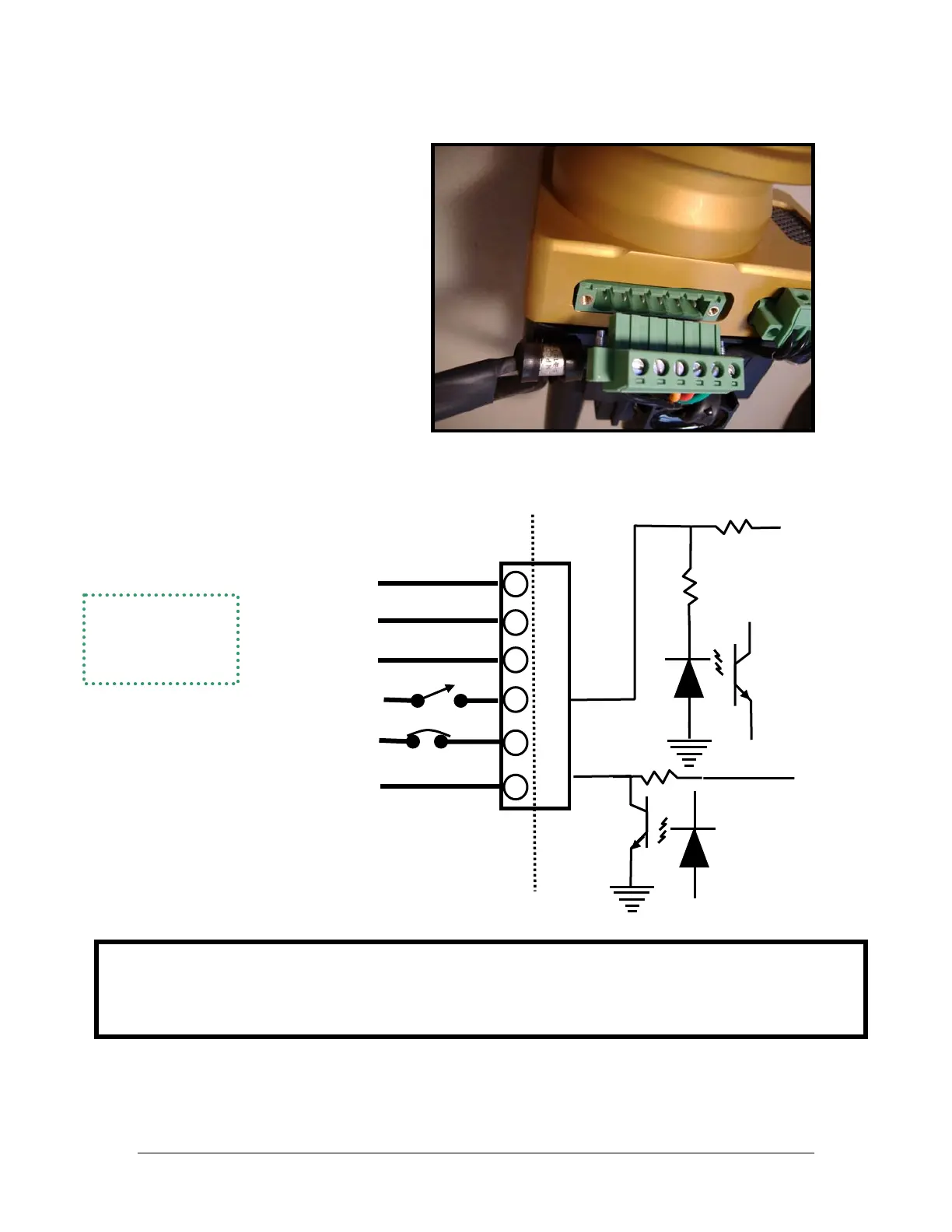
Connector Plug
(viewed from cage
screw side)
O
to Isolato
Opto Isolator
Inside
Case
Outside
Case
(Power and ground wiring should be
18 gauge. Other wires can be 20
gauge.)
+5 Volts
1. To ground on engine case
1
4. P-Lead (ignition switch to ground
stops ignition firing)
4
5. Aircraft Power (+13.8vdc) through
3(P-MAG) or 5(E-MAG) amp breaker
5
6. Optional Tack Output* - 12-volt
pulse 20 millisecond long - 2 ppr
6
2
Control Alternate
3
Jumpers 2 & 3
for low advance
– see Variable
Timing Limit
+12 Volts