10
E/One Grinder Pump Station Ballast Calculations
Any buried vessel that is submerged, or partially submerged, in water will be acted on by an upward
buoyant force that attempts to return the vessel to a non-submerged state. The magnitude of this
buoyant force is equal to the volume of the vessel that is submerged multiplied by the density of water.
On most in-ground installations a ballast, or concrete anchor, of proper volume and weight is required
to resist the buoyant force. The amount of ballast required for a given set of installation site conditions
may be calculated as follows.
Installation Site Assumptions
1. Low water table – under worst case ground water or ood conditions only the wet well portions of
the E/One grinder pump stations will be submerged.
2. Backll materials are per these installation instructions.
3. The consulting engineer should perform a soil test to determine if the assumptions that have been
made are valid. If the site conditions dier from these assumptions, then the consulting engineer
must revise the calculations as shown in this document.
Physical Constants
1. Density of Water = 62.4 lb/cu ft
2. Density of Concrete = 150 lb/cu ft (in air)
3. Density of Concrete = 87.6 lb/cu ft (in water)
4. Density of Dry Compacted Backll = 110 lb/cu ft
5. Density of Saturated Backll = 70 lb/cu ft
Procedure
A. Determine The Buoyant Force Exerted On The Station
1. Determine the buoyant force that acts on the grinder pump station when the wet well is
submerged in water.
2. Subtract the weight of the station from the buoyant force due to the submerged wet well to
determine the net buoyant force acting on the station.
B. Determine The Ballast Force Exerted On The Station
1. Determine the ballast force applied to the station from the concrete, saturated soil and dry soil
C. Subtract The Ballast Force From the Buoyant Force.
1. Note – if the installation site conditions are dierent from those listed above, the consulting
engineer should recalculate the concrete ballast.
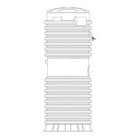
Ballast Calculations
The following calculations are to outline the areas used to determine the volumes of the dierent
materials for the ballast. All sections referred to in the calculations are marked on the accompanying
drawing.
 Loading...

