19
11. Attach the vent pipe extension with the 2” vent coupling, bringing the vent well above grade.
12. Clean all dirt and debris from top four corrugations on tank. Install the 24” coupler O-ring on the tank
between the top two corrugations with the white or yellow line facing out and on top.
13. Lube extension coupler and coupler O-ring with pipe lube or dish soap.
14. Manually press coupling evenly over lubricated O-ring. If additional force is needed, place a plywood
cover over the accessway and apply gentle mechanical pressure to the coupler. Note: Care must be used
when pushing down on the coupler. Excessive force or impact may result in damage and leakage.
15. Frequent visual inspections during installation must be performed to determine when the tank has fully
engage the coupler.
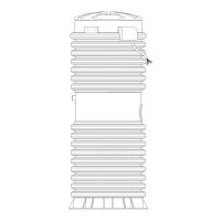
INSTALL REPLACEMENT COVER ASSEMBLY (Fig. 10)
16. Clean top corrugation on accessway extension and
mating surface of replacement shroud with acetone.
17. Liberally apply the silicone sealer provided to the
under side of the replacement shroud where it will come in
contact with the accessway extension.
18. Lube wet well vent grommet and vent pipe extension
with pipe lube, non-grit hand cleaner or dish soap and
slide vent pipe through grommet until tank shroud seats to
accessway.
19. Place SS band clamp around top corrugation and the
replacement shroud. Tap with a mallet around clamp to help
seat the clamp. Torque stud assembly on band clamp to a
maximum 125 inlb.
20. Reinstall the supply cable, EQD**, tank lid and
electrical shroud and tighten cable connector. (**See “EQD
wiring order,” Table 1)
21. Follow start-up procedures to ensure proper pump operation (you will
nd the start-up instructions in our service manual or the station installation
instruction guide).
PIN # COLOR
1 Brown
2 Red
3 Black
4 Grn/Yellow
5 Yellow
6 Blue
**EQD wiring order
Table 1
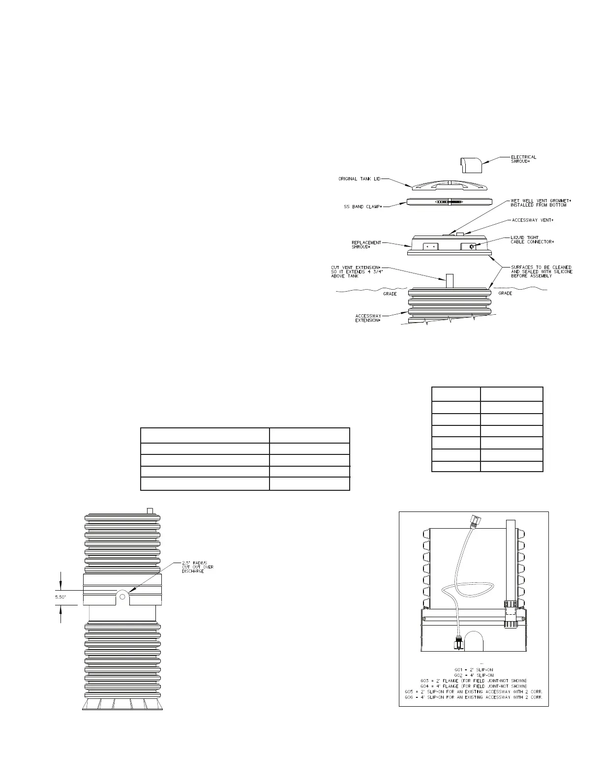
NOTE: IF EXISTING
ACCESSWAY HAS ONLY 2
CORRUGATIONS (Fig. 11)
- If the coupler will not
engage completely because the
discharge piping is in the way,
and it doesn’t have a cut out,
you will need to cut a slot in the
coupler.
- Using a hand, reciprocating
or hole saw, cut an arch in the
coupler; the cut-out is not to
exceed 5.50” tall or 5.00” wide.Figure 11 Figure 12
Table 2
Figure 10
NC0028
DESCRIPTION PART NO.
Simplex station NC0022G15
Simplex, ood plain cong NC0022G16
Duplex station NC0022G17
Duplex, ood plain cong NC0022G18
 Loading...

