11
Field Joint Assembly Instructions
Parts included in Field Joint Kit:
Identify all parts before proceeding
with installation.
(16) 3/8-16 X 2” long screws
(16) 3/8-16 Elastic Stop Nuts
(32) Flat Washers
(1) Length Sealant (Sika) Tape
(1) Hole Punch
1) Carefully clean and dry
both accessway anges and
the tank top ange with solvent.
IMPORTANT: Sealing surfaces
must be dry to ensure the
sealant adheres correctly.
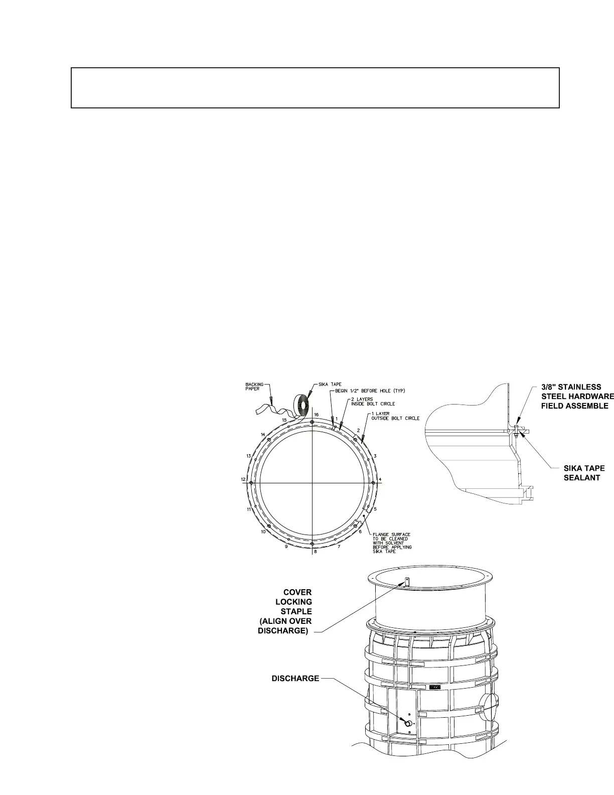
2) Starting at one hole of tank
ange, apply two layers of Sika
Tape around the ange. Align the
outside edge of the tape with the
bolt circle. Move to the adjacent
hole and apply one layer of Sika
Tape around the outside of the
ange. Align inside of tape with the
bolt circle. Remove the backing
paper as you lay the adhesive
on the ange. Do not stretch
Sika tape during application,
it may result in a leak. The
tape should overlap at the end
by approximately 1/2 inch, as
shown in Figure 6a. If a section
of Sika Tape is misapplied, the
bad section may be cut out and
replaced. Cut away the poorly laid
portion cleanly with a knife and be
sure to over lap the tape at each
end about 1/2 inch.
3) Using the tool provided,
punch a hole through the tape at
each of the 16 existing bolt holes
in the ange. Be careful to keep
the exposed sealant clean and
dry.
4) Insert three of the sixteen
3/8-16 x 2” long bolts, with a at
washer, into the ange attached to
the lower end of the accessway.
These will act as guides while
aligning the bolt pattern of the two
anges.
5) Support the upper accessway
section a few inches over the tank.
Align the aluminum cover locking
hasp on the berglass accessway
section with the stainless steel
discharge connection on the
polyethylene tank (Figure 6b).
Once aligned, lower the upper
section onto the mating ange
using the three bolts to guide it to
the proper position. See Figure 6c.
6) Insert the remaining 13 bolts
with at washers into the anges.
Place a at washer and elastic
stop nut on the end of each bolt,
turning the nut on just enough to
hold the washer in place.
7) Tighten up the bolts until
the sealant begins to squeeze
out from between the anges.
To ensure a consistent, sturdy
seal tighten them in the following
sequence: 1, 9; 5, 13; 3, 11; 7, 15;
2, 10; 4, 12; 6, 14; 8, 16. Always
be sure to tighten one bolt and then
the bolt at the position 180° from it,
see Figure 6a for position numbers.
8) Using the same sequence as
in step 7 tighten each bolt to 60 in-
lbs. Visually inspect the joint, each
bolt and each nut should have a at
washer between it and the ange,
and a uniform amount of sealant
should be protruding from the seam
along the entire perimeter.
In the event that there are
any voids in the sealant, the
joint may leak. Take corrective
actions if necessary and be sure
that the joint is leak free before
continuing.
IT IS EXTREMELY IMPORTANT THAT THE JOINT IS SEALED PROPERLY BEFORE BACKFILLING.
EXCAVATING A UNIT FOR REPAIR IS VERY EXPENSIVE AND CAN BE EASILY AVOIDED BY USING
PROPER CAUTION DURING THE FOLLOWING PROCEDURE.
Figure 6a Figure 6c
Figure 6b
 Loading...

