5
the soil conditions and must
be in accordance with the site
engineer’s recommendation
and safety requirements. Care
must be taken during lifting and
placement to prevent impacting
or otherwise damaging the tank
(see Lifting Instructions). Only
a non-marring sling, rated for
the load being lifted, should
be used in contact with the
tank surfaces. A pre-ballasted
tank must not be lifted with a
sling (see Lifting Instructions).
Lifting chains or cables should
not be placed in direct contact
with the tank surfaces. Fill the
excavation bottom with a 6”
deep bed of gravel, naturally
rounded aggregate, clean and
free owing, with particles not
less than 1/8” or more than 3/4”
in size.
A concrete ballast anchor is
required to prevent otation of
the tank when groundwater is
present. The concrete anchor
is not optional. The MINIMUM
concrete anchor requirements
for the WH/WR48 station are
shown in Chart 1 of the Ballast
Calculation section in this
manual. Pour approximately
1” to 2” of concrete onto the
gravel bed and place the tank
into the excavation. Ensure the
tank is properly positioned in
the excavation to support inlet
pipe (Section 3) and discharge
pipe (Section 5) connections
before pouring the concrete
ballast. The unit should be
leveled and lled with water,
about 24” deep, to prevent
shifting while the remaining
ballast is being poured. The
concrete should be vibrated, as
necessary, to eliminate voids.
If it is necessary to pour the
concrete above the inlet level
(Section 3), the inlet must be
sleeved with an 8” tube before
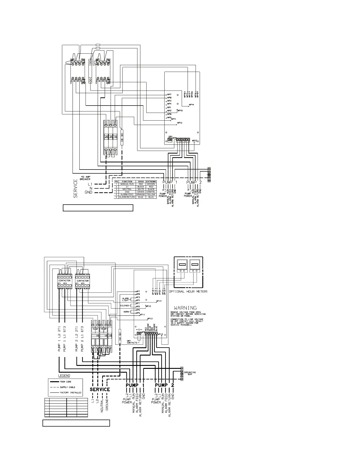
PI N FUNCTI ON 2000S EXTREME
1 MA NUAL RUN RED BROWN
2 L1 BLACK RED
3 L2 WHITE BLA CK
4 GND GREEN GRN/YEL
5 ALARM FEED ORANGE YELLOW
6 ALA RM RE TURN BLUE BLUE
PI N FUNCTI ON 2000S EXTREME
1 MA NUAL RUN RED BROWN
2 L1 BLACK RED
3 L2 WHITE BLA CK
4 GND GREEN GRN/YEL
5 ALARM FEED ORANGE YELLOW
6 ALA RM RE TURN BLUE BLUE
PI N FUNCTI ON 2000S EXTREME
1 MA NUAL RUN RED BROWN
2 L1 BLACK RED
3 L2 WHITE BLA CK
4 GND GREEN GRN/YEL
5 ALARM FEED ORANGE YELLOW
6 ALA RM RE TURN BLUE BLUE
240 VOLT WIRING – DUPLEX
Figure 2d
120 VOLT DUPLEX WIRING
A DEDICATED 40A CIRCUIT BREAKER
Figure 2d
A DEDICATED 30A CIRCUIT BREAKER
 Loading...

