7
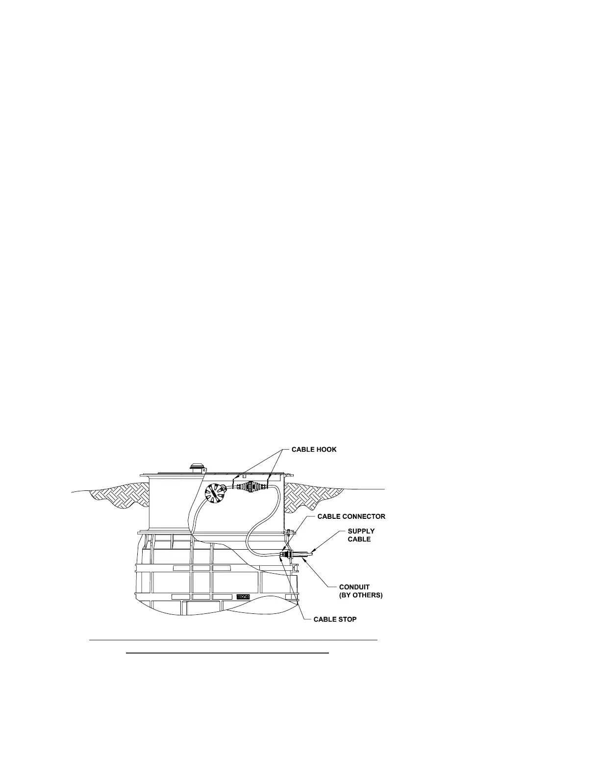
Figure 4
TYPICAL SUPPLY CABLE CONFIGURATION
and does not require the use of
additional sealant or adhesive.
4. INLET PIPE
INSTALLATION: Mark the
inlet pipe 3.5” from the end to
be inserted. Inlet pipe leading
edge should be beveled with
a grinder and lubricated with
a soap solution. Lubricate
the inlet grommet with soap
solution as well. Insert the pipe
into the grommet up to the 3.5”
mark. Inspect to ensure the
grommet has remained intact
and in place (Figure 7).
5. DISCHARGE: The use
of 1.25” PVC pressure pipe
SCH 40 and polyethylene
pipe SDR 11 or SIDR 7 are
recommended. If polyethylene
is chosen, use compression-
type ttings to provide a
smooth inner passage.
E/One requires that an
E/One Uni-Lateral assembly
(E/One part number
NB0184PXX or NC0193GXX)
or E/One Redundant Check
Valve (E/One part number
PC0051GXX) be installed in
the pipe lateral outside the
home between the pump
discharge and the street main
on all installations. Never use
a ball-type valve as a check
valve. E/One recommends
the valve be installed as close
to the public right-of-way as
possible. Check local codes for
applicable requirements.
CAUTION: Redundant check
valves on station laterals
and anti-siphon/check valve
assemblies on grinder pump
cores should not be used as
system isolation valves during
line tests.
There is a slide face valve(s)
and a quick disconnect(s)
pre-installed in the tank for
each grinder pump connection.
There is a stainless steel
1.25” NPT female discharge
connection(s) on the outside of
the tank to support discharge
piping connection.
Note: Models 481 and 482
will have single discharge pipe
connection; models 483 and
484 will have two discharge
pipe connections 180 degrees
apart (standard).
6. BACKFILL
REQUIREMENTS: Proper
backll is essential to the
long term reliability of any
underground structure.
Several methods of backll are
available to produce favorable
results with different native soil
conditions.
The recommended method
of backlling is to surround
the unit to grade using Class
I or Class II backll material
as dened in ASTM 2321.
Class 1A and Class 1B are
recommended where frost
heave is a concern; Class
1B is a better choice when
the native soil is sand or if a
high, uctuating water table
is expected. Class I, angular
crushed stone, offers an added
benet in that it needs minimal
compaction. Class II, naturally
rounded stone, may require
more compactive effort, or
tamping, to achieve the proper
density.
If the native soil condition
consists of clean compactible
soil, with less than 12% nes,
free of ice, rocks, roots, and
organic material, it may be
an acceptable backll. Such
soil must be compacted in
lifts not to exceed one foot to
reach a nal Proctor Density
between 85% and 90%. Non-
compactible clays and silts are
not suitable backll for this
or any underground structure
such as inlet or discharge
lines. If you are unsure of
the consistency of the native
soil, it is recommended that a
geotechnical evaluation of the
material be obtained before
specifying backll.
Another option is the use of
Power at the station must not drop below 10% of nameplate
voltage. Maximum Recommended Length:
120 Volt 60’ (min. voltage at pump — 108V)
240 Volt 150’ (min. voltage at pump — 216V)
Consult factory for longer lengths
 Loading...

