Notes
1. If the 10 MHz signal is too low or not present.
2. The upconverter also contains its own stabilised internal reference that enables it
to be used without an external 10 MHz locking signal. This feature is activated
automatically when the external 10 MHz locking signal is too low or not present.
Basic Upconverter Specification
Output frequency:
UA variants ..................... 14.0 to 14.5 GHz
UB variants .................... 13.75 to 14.5 GHz
Input frequency:
UA variants ..................... 950to1450 MHz
UB variants ..................... 950to1700 MHz
L-band input level:
minimum .........................710 dBm
maximum .......................... 0dBm
External locking signal.......... 10MHz(0dBmmax, 75 dBm min)
fed through IF cable
Stability using internal 10 MHz reference .............. 2ppm
Notes
1. When using amplifiers fitted with both an upconverter and a digital electronically
variable attenuator (DEVA) (e.g. N6315DUB, N6318DUA etc), the L-band input drive
level should be set between 710 and 0 dBm and the DEVA control used to adjust the
amplification. For any upconverted amplifier, if the L-band input level is too high, the
mixer can be driven into saturation and intermodulation products may be
experienced.
If the L-band input level is too low (5720 dBm), signal mixing will be poor,
possibly with intermittent signal locking.
2. If the wider band (750 MHz) UB variant is used with exciter chain equipment that
is operating over a narrower band (500 MHz), the lowest frequency reference point
will be 13.75 GHz, resulting in an output frequency range of 13.75 to 14.25 GHz and
not the desired 14.0 to 14.5 GHz.
4.5 RF Sample Port
Provided as an optional N-type (female) connector, mounted at the opposite end of
the amplifier to the waveguide flange. It allows external monitoring of the output
power, providing a signal approximately 50 dB lower than the RF output power. It is
provided with calibration data across the amplifier’s frequency range.
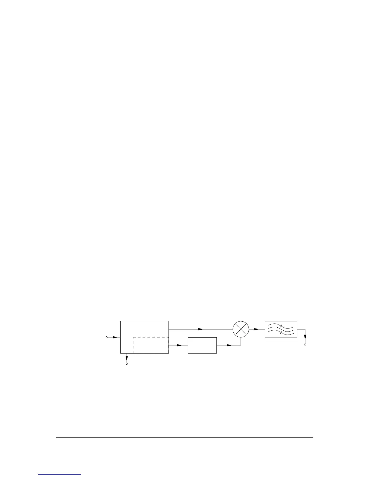
DEMODULATOR
10 MHz TO 50 MHz
FREQUENCY
MULTIPLIER
PHASE
LOCKED
OSCILLATOR
INPUT
L-BAND
& 10 MHz
UPCONVERTER FAULT
MIXER BANDPASS FILTER
OUTPUT
50 MHz 13.05/12.80 GHz
950 TO 1450/1700 MHz
HBN63xx-1, Issue 8, Page 19