EasyManua.ls Logo

EARDATEK KINGSAT KM-V3 - User Manual

EARDATEK KINGSAT KM-V3
29 pages
Print Icon
To Next Page IconTo Next Page
Loading...
KINGSAT Satellite TV Antenna System
1
www.kingsat-tech.com
sales@kingsat-tech.com
Question and Answer IconNeed help?

Do you have a question about the EARDATEK KINGSAT KM-V3 and is the answer not in the manual?

Summary

Introduction to KINGSAT Satellite TV Antenna System

Overview and Key Features

Provides an overview of the KINGSAT KM-V3/V4/V6/V7 system and its main features.

KINGSAT Antenna Installation Guide

Preparation for Installation

Details the standard components and tools required for the KINGSAT antenna installation process.

Planning the Antenna Installation

Outlines procedures for optimal antenna placement, considering clear horizon and avoiding obstacles.

Installation and Mounting of Antenna

Provides general guidelines and confirmation steps for installing and mounting the antenna unit.

Confirming Antenna Mounting Position

Details how to confirm the antenna mounting position using templates and ensuring a flat surface.

Connecting the Antenna Cable

Explains the procedure for connecting the RF cable to the antenna base plate using an adjustable spanner.

Mounting the Antenna Unit

Describes the method for attaching the antenna unit using supplied hardware like hex head bolts and washers.

Installing the ACU

Provides instructions for selecting a site and mounting the Antenna Control Unit (ACU).

KINGSAT Satellite TV Antenna Operation Guide

Introduction to ACU Operation

Provides an overview of the ACU functions and the main menu structure.

ACU Interface and Controls

Explains the soft keys, buttons, and basic interface of the Antenna Control Unit (ACU).

Normal Operation Modes

Details system startup sequences, satellite search, and automatic sleep mode functionality.

Changing Target Satellite

Guides users on selecting and tracking different target satellites.

Setup Mode: Satellite List Configuration

Covers configuring the satellite list within the ACU's Setup Mode.

Setup Mode: LNB Information Settings

Details the configuration of LNB type, polarization, and local frequency in Setup Mode.

Setup Mode: GPS Coordinate Configuration

Explains how to set and modify GPS coordinates for optimal antenna performance.

Setup Mode: Editing Satellite Data

Guides on modifying existing or inputting new satellite data, including tracking parameters.

Setup Mode: DiSEqC 1.0 Functionality

Details how to enable and disable the ACU's DiSEqC 1.0 protocol for satellite switching.

Setup Mode: Resetting to Default

Provides instructions for resetting all ACU parameters to their default factory settings.

Monitoring and Diagnostics

Explains how to check antenna status, power, GPS, signal, and software version through diagnostics.

Troubleshooting: Error Codes and Solutions

Lists common error codes and their corresponding troubleshooting steps for the KINGSAT system.

KINGSAT Antenna Preparation for Transportation

Securing the Antenna for Transport

Describes procedures to secure the antenna internally to prevent damage during transportation.

Overview

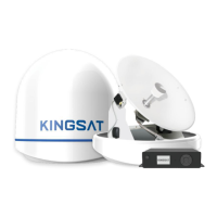
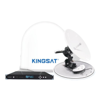
The KINGSAT KM-V3/V4/V6/V7 is a series of digital satellite TV antenna systems designed for maritime use, enabling automatic search, tracking, and capture of satellite signals from Digital Video Broadcasting (DVB) compatible satellites. These systems are manufactured by EARDATEK.

Function Description

The KINGSAT KM-V3/V4/V6/V7 antenna system provides stable satellite TV reception on various types of vessels. It automatically tracks and locks onto satellite signals, ensuring continuous entertainment even in challenging marine environments. The system includes an Antenna Unit (AU) and an Antenna Control Unit (ACU) for managing operations and settings.

Important Technical Specifications

Antenna Unit (AU):

  • Models: KM-V3, KM-V4, KM-V6, KM-V7
  • Dimensions (Radome):
    • KM-V3: 41 cm (diameter), 42 cm (height)
    • KM-V4: 54 cm (diameter), 56.5 cm (height)
    • KM-V6: 73 cm (diameter), 76 cm (height)
    • KM-V7: 82 cm (diameter), 86 cm (height)
  • Mounting Hole Positions:
    • KM-V3: 20 cm (diameter)
    • KM-V4: 23 cm (diameter)
    • KM-V6: 30.5 cm (diameter)
    • KM-V7: 40 cm (diameter)
  • RF Connectors: RF1 (necessary), RF2, RF3, RF4 (for multiple receivers)
  • Mounting Hardware: Hex head bolts (M8 for V3/V4/V6, M12 for V7), spring washers, flat washers, nuts, mounting brackets, tapping screws.

Antenna Control Unit (ACU):

  • Dimensions: 17.7 cm (width), 13.4 cm (height), 5.0 cm (depth), 1.8 cm (front panel protrusion)
  • Power Supply: 110-240V AC
  • Cable Connections: ANT-RF1 (to antenna), RECEIVER (to TV/receiver), POEWR (power input)
  • Interface: Soft keys (POWER, MONITOR, LEFT, UP, OK, RIGHT, ENTER, DOWN) and a display screen.

Cables:

  • Coaxial Cable: 15-meter length supplied (longer lengths available from Earda Technologies). Exceeding indicated length may reduce performance.
  • Power Cable: 1 supplied.

LNB Types (for reference):

  • Single Band LNB:
    • Asia: 11300MHz
    • America: 11250MHz
    • Japan: 10678MHz
    • Korea: 10750MHz
  • Universal LNB:
    • Low band local frequency: 9750MHz
    • High band local frequency: 10600MHz

Usage Features

Strong Signal Receiving Performance: Utilizes self-made LNB and RF processing components to ensure optimal reception quality and maximum antenna performance.

Fast Satellite Search and Position: Features an integrated GPS antenna that automatically updates GPS data for accurate positioning and quicker satellite locking.

Excellent Anti-Heavy Sea Tracking Ability: Incorporates a proprietary algorithm, advanced mechanical design, embedded GPS, and a high-sensitive gyro to maintain continuous connectivity and enable worldwide deployment, even in heavy seas.

Expendable Worldwide Satellite Library: The ACU comes pre-installed with a worldwide satellite database, which can be easily revised or expanded manually by the user.

Easy-to-install Aesthetic Design: Designed for simple installation and setup, featuring an aesthetic maritime white finish and environment-resistant properties, which helps reduce labor and maintenance costs.

Multi-Receivers Solution: Supports multiple receivers by integrating a suitable Multi Switch (not supplied) between the antenna and the receivers. The system can connect up to four RF outputs (RF1, RF2, RF3, RF4) to the Multi Switch.

ACU DiSEqC 1.0 Function (Additional Version): Allows the ACU to support DiSEqC 1.0 protocol, enabling easy switching between 1-4 satellites from a receiver's DiSEqC 1.0 command. This requires the ACU satellite list to be matched with the receiver's DiSEqC 1.0 port configuration.

Normal Mode Operations:

  • Start Up: The ACU screen displays sequences for brand recognition, data communication establishment, antenna initialization, satellite search, and satellite lock/tracking.
  • Sleep Mode: The antenna automatically enters sleep mode after 8 minutes of not locking onto a satellite and wakes up automatically after 10 minutes or when the target satellite is changed.
  • Change Target Satellite: Users can easily select from up to 6 pre-programmed satellites, and the antenna will automatically search and track the new target.

Setup Mode Operations:

  • Set Sat List: Allows users to change and configure pre-programmed satellites (SAT 1 to SAT 6) by selecting from a list and saving the changes.
  • Set LNB Info: Enables setting LNB type (UNIVERSAL/SINGLE) and polarization (LINEAR/CIRCULAR), and inputting local frequency (HIGH/LOW) values. This mode is not recommended for novice users.
  • Set GPS: Allows manual input and modification of GPS longitude and latitude information to enhance antenna functionality and positioning performance.
  • Edit Sat Info: Provides options to modify existing satellite information or input new satellite parameters, including satellite name, longitude, tracking TP settings (frequency and symbol rate for High-band Vertical, Low-band Vertical, High-band Horizontal, Low-band Horizontal), SKEW OFFSET (recommended +00DEG), and LNB VOLTAGE SUPPLY METHOD (18V-Hor/L, 13V-Ver/R, Bypass). This mode is not recommended for users unfamiliar with satellite parameters.
  • Set to Default: Resets all system parameters back to their default settings.

Monitor/Diagnost Mode:

  • Allows checking the antenna's diagnostic self-test results, including:
    • View Power: Displays the power status.
    • View Band: Checks the status of 0/22K.
    • View GPS: Checks the GPS status.
    • View Sat Signal: Displays the satellite signal status.
    • Software Version: Shows the current software version.

Maintenance Features

Cable Protection: All cables must be properly clamped and protected from physical damage, heat, and humidity. Excessive bending of cables should be avoided. Watertight grommets or swan neck tubes should be used where cables pass through exposed bulkheads or deck heads.

Antenna Mounting: The mounting platform must be firm and free from excessive vibration. The antenna should be installed with a clear, all-around view of the horizon and no obstacles within 1 degree above it. It should also be placed far from radar systems (minimum 1.2m/4ft clearance from radar beam).

Connector Care: When connecting RF cables, users should be careful not to overtighten and damage the connectors. Connectors should not touch the mounting surface of the antenna to prevent critical malfunctions and damage.

Error Code and Solutions: The system provides error codes (E01-E08) to assist in troubleshooting:

  • E01: Antenna control board initialization failed.
  • E02: Antenna input power test failed (check RF cable).
  • E03: Skew system test failed (check control board, skew motor).
  • E04: Tuner test failed (check tuner and cable connection).
  • E05: LNB test failed (check LNB and control board).
  • E06: Gyro board test failed (check gyro board, cable connection).
  • E07: EL axis test failed (check limit sensors, motor, and belt for EL axis).
  • E08: AZ axis test failed (check limit sensors, motor, and belt for AZ axis).

Preparation for Transportation: Specific procedures must be followed to secure the antenna internally to prevent damage during transport:

  1. Rotate the antenna left and right slowly until the limit switch is pressed.
  2. Turn the antenna 360° in the reverse direction.
  3. Insert shipping foams in front of the dish and on the back side of the pedestal to secure it to the pedestal and bottom radome.
  4. Cover the upper part of the radome, being careful not to touch the reflector.
  5. Pack the KINGSAT KM-V3/V4/V6/V7 into its original package box.

EARDATEK KINGSAT KM-V3 Specifications

General IconGeneral
BrandEARDATEK
ModelKINGSAT KM-V3
CategoryAntenna
LanguageEnglish

Related product manuals