OPERATOR INSTRUCTIONS AND PARTS
CRT Models 6014V
Page 11
800-345-6007
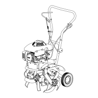
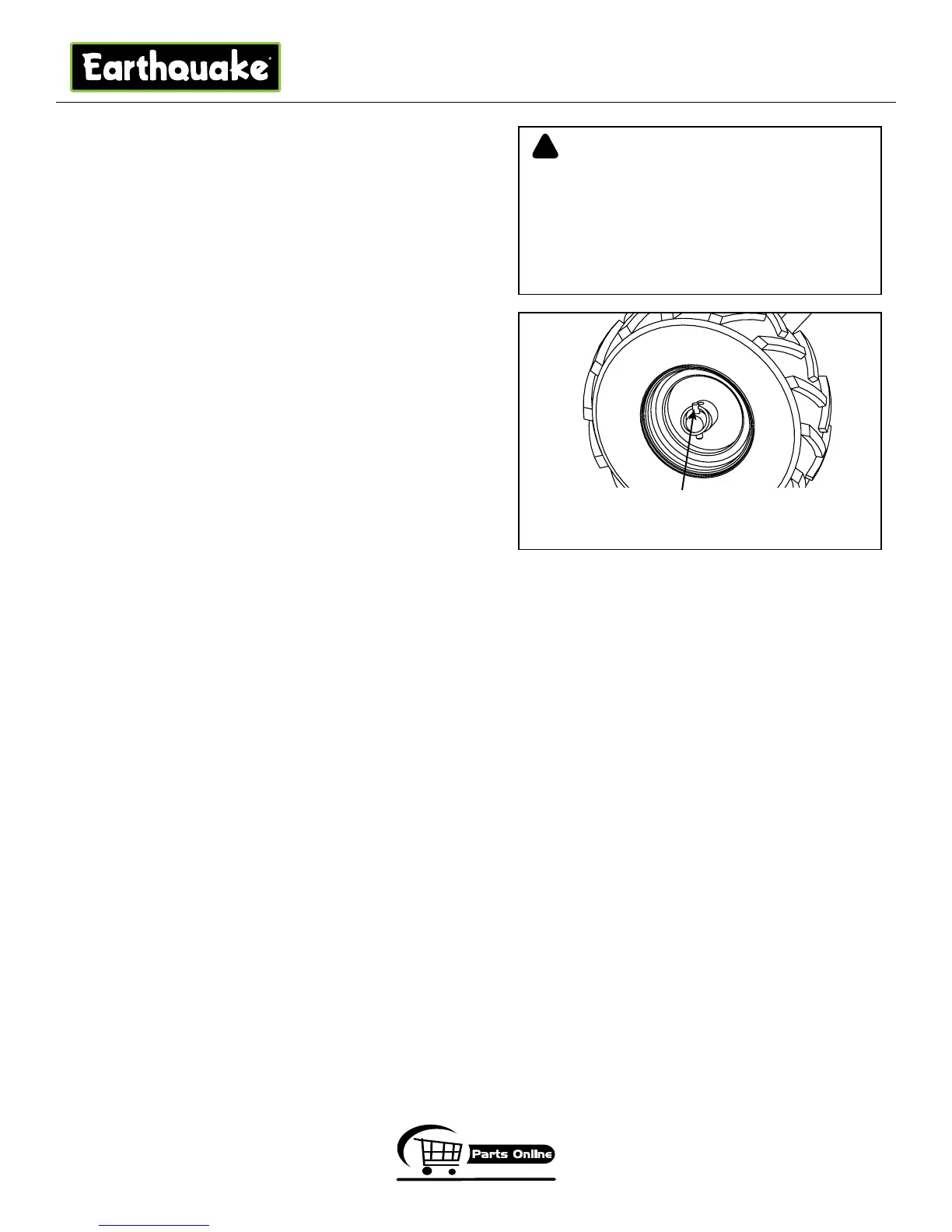
WHEEL LOCK PINS
Place wheels in tilling position.
1. Remove lock pin. Align hole in axle with hole in wheel hub.
(SEE
FIGURE 2)
2. Insert lock pin through holes, fold lock pin ring to secure pin to
axle.
3. Firmly lock wheel and axle together before tilling.
4. Repeat for other wheel.
NOTE: Always have both wheel lock pins in or out. Do not
operate tiller with only one wheel locked.
To place wheels in free-wheel position.
1. Remove lock pin. Slide wheel inward toward machine.
2. Insert pin in axle only.
3. Wheel should turn freely on axle.
Wheel lock pin in free-wheel position.
(axle hole only)
NEVER START ENGINE OR OPERATE TILLER
WITH WHEELS IN FREE-WHEEL POSITION. THE
FREE-WHEEL POSITION IS FOR TRANSPORTING
THE TILLER LONG DISTANCES OVER LEVEL
GROUND-DO NOT ATTEMPT TO MOVE THE TILLER
UP OR DOWN STEEP GRADES IN THE FREE-WHEEL
POSITION.
WARNING
!
FIGURE 2
 Loading...