Do you have a question about the East Tester ET4401 and is the answer not in the manual?
Details regarding power supply voltage, frequency, and grounding requirements.
Detailed technical specifications including power, environment, dimensions, and mass.
Identifies and describes the components on the front panel of the LCR meter.
Details the specific functions of various keys like LEVEL, FREQ, RANGE, etc.
Explains the layout and elements of the main measurement display screen.
Describes the interface used for configuring measurement parameters.
Details the interface for system-wide configurations like language and backlight.
Steps to select the test frequency for measurements.
Instructions on how to set the test signal level.
Procedures for selecting the measurement range automatically or manually.
How to switch between primary measurement parameters like R, C, L, Z.
Configuration of the comparator function, including nominal value and tolerance.
Setting the tolerance limits for the comparator.
How to perform open circuit and short circuit corrections for accuracy.
Provides the accuracy specifications under various conditions.
Specific accuracy figures for DC Resistance measurements.
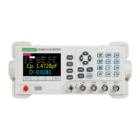
The ET44 Series Benchtop Digital Bridge is a sophisticated LCR meter designed for precise component measurement and analysis. This series, exemplified by the ET4401, ET4402, and ET4410 models, integrates a 3.5-inch TFT display with a user-friendly interface, offering a comprehensive suite of features for both manual operation and remote control.
The ET44 series benchtop digital bridge is primarily used for measuring various electrical parameters of components. It supports the measurement of inductance (L), capacitance (C), resistance (R), and impedance (Z) as main parameters. Secondary parameters include reactance (X), loss (D), quality factor (Q), impedance angle (θ), and equivalent series resistance (ESR). The device also supports DC resistance (DCR) measurement and electrolytic capacitor mode.
A key feature is its comparator function, which allows for component sorting based on user-defined nominal values and tolerance limits. This is particularly useful in production environments for quality control. The instrument can perform list scanning, enabling circulated scanning over multiple frequencies and comparison with nominal values.
Data recording capabilities include capturing maximum, minimum, and average values of measurements over a period. It also offers a data retention function to hold current measurement values. Correction functions for open circuit and short circuit are available to ensure measurement accuracy by compensating for stray admittance and residual impedance caused by test fixtures.
The device supports both series (SER) and parallel (PAR) equivalent modes, allowing users to choose the appropriate circuit model based on the component type and application. For instance, series equivalent circuits are recommended for low-value impedance elements (high-value capacitance and low-value inductance), while parallel equivalent circuits are suitable for high-value impedance elements.
The ET44 series boasts a basic accuracy of 0.2%. It features a 3.5-inch TFT display with 5 and a half bits for main parameter display and 5 digits for secondary parameters.
Measurement Ranges:
Test Frequencies:
Test Signal Level:
Internal Bias Voltage Output:
Output Impedance:
Measurement Display Speed:
Power Supply:
Dimensions:
Communication Interfaces:
The ET44 series is designed for ease of use with a clear front panel layout. Front Panel Controls:
User Interface: The display is organized into pages for measurement display, measurement setting, and system setting. The measurement display shows the main and secondary parameters, current settings (level, frequency, bias, range, compensation, resistance, speed, list status), and a message column for data automation/retention, relative display, and MAX/MIN/AVG labels/values.
Parameter Selection: Users can easily select test frequency, level, offset (bias), range, output impedance, and measurement speed using dedicated keys and direction buttons. The offset value can be precisely adjusted digit by digit.
Comparator Setting: The comparator allows setting a nominal value and tolerance limits. It provides visual feedback (e.g., "BIN: 1" for qualified, "OUT" for unqualified, "AUX" for secondary parameter failure) and supports five-gear sorting.
System Settings: The instrument allows configuration of language (Chinese, English), backlight brightness (30%, 50%, 70%, 100%), power-on parameter settings (default or previous value), and buzzer switch (ON/OFF).
Installation and Environment:
Warm-up and Continuous Working Hours:
Correction Function: The open circuit and short circuit correction functions are crucial for maintaining measurement accuracy. These compensate for stray admittance and residual impedance introduced by the test fixture. The calibration process is guided through the interface, indicating success or failure.
Warranty: The instrument should only be maintained and repaired by professional technical personnel. Unauthorized replacement of components is not covered under warranty, and users will bear the cost of such maintenance. After any maintenance, a new measurement and calibration should be performed to ensure test accuracy.
| Model | ET4401 |
|---|---|
| Manufacturer | East Tester |
| Type | LCR Meter |
| Measurement Parameters | L, C, R, D, Q, θ, Z |
| Frequency Range | 100Hz, 120Hz, 1kHz, 10kHz, 100kHz |
| Measurement Range (R) | 0.0001Ω |
| Test Level | 0.3V |
| Calibration Function | Open/Short |
| Operating Environment | 0~40℃ |