EasyManua.ls Logo

Eastwood 51118 User Manual

Eastwood 51118
16 pages
To Next Page IconTo Next Page
Page #1 background imageLoading...
Page #1 background image
ABRASIVE BLASTER
ASSEMBLY & OPERATING INSTRUCTIONS
Eastwood Item Numbers 51117, 51118, 51119
© Copyright 2014 Easthill Group, Inc. Instruction part #51116Q Rev. 6/14
If you have any questions about the use of this product, please contact
The Eastwood Technical Assistance Service Department: 800.544.5118 >> email: techelp@eastwood.com
PDF version of this manual is available online >> eastwood.com/51116manual
The Eastwood Company 263 Shoemaker Road, Pottstown, PA 19464, USA
US and Canada: 800.345.1178 Outside US: 610.718.8335
Fax: 610.323.6268 eastwood.com
ACCESSORIES
#22022 Abrasive Sifter Screen, 11"
#50417 Abrasive Media Funnel Strainer, 8"
#12123 Blast Nozzle Sealing Pads, 3 Pack
#51556 2mm Blast Nozzle, 3 Pack
#12111 2.5mm Blast Nozzle, 3 Pack
#12112 3mm Blast Nozzle, 3 Pack
#51557 3.5mm Blast Nozzle, 3 Pack
#11780 Replacement Safety Trigger Assembly (Deadman Valve)
#13792 Aluminum Oxide Abrasive Media, 90 Grit, 50-lbs.
#22019 Silicon Carbide Abrasive Media, 60 Grit, 50-lbs.
#22023 Glass Bead Abrasive Media, 70/100 Grit, 50-lbs.
#51360 Soda Blasting Retrot Kit
# 51117
50-lb. Blaster
# 51118
100-lb. Blaster
# 51119
200-lb. Blaster
Question and Answer IconNeed help?

Do you have a question about the Eastwood 51118 and is the answer not in the manual?

Eastwood 51118 Specifications

General IconGeneral
BrandEastwood
Model51118
CategoryPaint Sprayer
LanguageEnglish

Summary

SAFETY INFORMATION

READ INSTRUCTIONS AND HAZARDS

Thoroughly read manual, understand applications, limitations, and potential hazards.

HEALTH AND SAFETY PRECAUTIONS

Wear protective gear, avoid silica abrasives, use safety equipment, and follow warnings.

OPERATIONAL HAZARDS

Includes securing workpiece, trigger safety, pressure release, maintenance checks, and air supply.

SPECIFICATIONS AND PARTS

TANK VOLUME AND AIR REQUIREMENTS

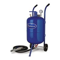
Details tank capacities, hose, nozzle, CFM, and abrasive supply requirements.

PARTS LIST

Comprehensive list of all included components for the abrasive blaster.

ASSEMBLY INSTRUCTIONS

INITIAL ASSEMBLY STEPS

Unpacking, attaching handle bars, and sliding the axle into place.

FINAL ASSEMBLY STEPS

Attaching wheels, hoses, support leg, air inlet, pressure gauge, and fittings.

OPERATION AND LOADING

ABRASIVE SELECTION AND LOADING

Guidance on choosing, preparing, and safely loading abrasive media into the tank.

BEGINNING ABRASIVE BLASTING

Connecting air, setting valves, adjusting flow, and starting the blasting process.

STOPPING AND MAINTENANCE

STOPPING BLASTING AND RELEASING PRESSURE

Procedure to safely stop blasting and release all pressure from the tank.

NOZZLE AND SEAL PAD REPLACEMENT

Instructions for replacing the blaster nozzle and its seal pad.

ROUTINE MAINTENANCE

MAINTENANCE PROCEDURES

Tasks like draining water trap, cleaning, checking for leaks, and component wear.

TROUBLESHOOTING

COMMON ISSUES AND SOLUTIONS

Addresses tuning, media clumping, and insufficient CFM for optimal performance.

WARRANTY INFORMATION

PRODUCT WARRANTY AND RETURNS

Details the one-year warranty, return process, and contact information.

ACCESSORIES

AVAILABLE ACCESSORIES

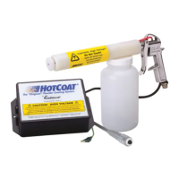
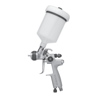
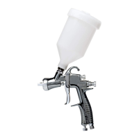
List of optional accessories and abrasive media for the blaster.

Related product manuals