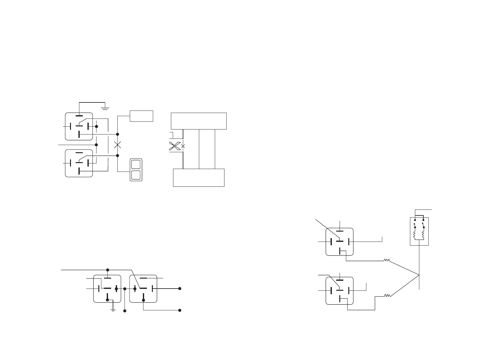
Type E: Electrically-activated vacuum systems.
Polarity reverses on a single wire to lock and unlock. Please set the door lock time to 3.5 seconds
by a timer delay switch (not included).
The door locks are controlled by an electrically activated vacuum pump. The control wire will show
+12v when doors are unlock and (-) ground when locked.
The vehicle must have a vacuum actuator in each door. Making sure that locking the doors from
the driver’s or passenger side using the key activates all the actuators in the vehicle. This requires
a slight modification to the door lock wire harness.
NOTE: For this kind of central door locking, must program the lock pulse time to be 3.5 seconds.
L
UL
SWITCH
LOCK/UNLOCK SWITCH
87
86
85
87a
30
87
86
85
87a
30
+12V
white/black lock
wire from EC003
white unlock
wire from Ec003
CUT
VACUUM PUMP
Inside pneumatic
lock main engine
Main wire
green/blue
Brown
Negative wire
Red/blue
positive wire
Door lock/unlock switch
This types of central door locking system mainly for Japanese driven
Single wire in series negative trigger.
Type F: One-wire system: cut to lock, ground to unlock.
Single wire that pulses negative to unlock, and open circuit to lock.
This type of door lock system usually requires a negative pulse to unlock, and cutting the wires to
lock the door. (for some vehicles, these are reversed). 2 extra SPDT relays are used to interface to
this type of system.
87
86
85
30
white unlockwire
fromEc003
86
85
87a
30
Single wire (open=lock/ground=unlock)
Door lock module
side cut wire
fused (+) 12V
Door switch side of cut wire
Unlock relay
LOCK relay
white/black lock
wire (-) from ec003
Not use
87a
87
Not use
Type G: Positive (+) multiplex. One wire controls lock and unlock using resistor(s).
4.Once the resistor value(s) is determined, refer to the wring diagram for proper wiring.
Single-resistor style: if one resistor is used in the door lock switch/key cylinder, the wire will pulse
(+) 12V in one direction and less than +12V when operated in the opposite direction.
1.Cut the output ire from the door lock switch/key cylinder in half;
Determining the proper resistor values: to determine the resistor values, the door lock
switch/key cylinder must be isolated from the factory door lock system. For testing, use a calibrated
digital multi-meter that is set to ohms.
Single wire positive central locking
IMPORTANT: to ensure an accurate resistance reading, do not touch the resistor or leads during
testing.
Two resistor type: if two resistors are used in the factory door lock switch/key cylinder, the
switch/key cylinder will read less than +12V in both directions.
2.Test with the meter from the switch side of the cut door lock switch/key cylinder wire to a reliable
constant +12V source. Some good constant +12V references are the power input source to the
door lock switch/key cylinder, the ignition switch power wire, or the (+) terminal of the battery.
3.Operate the door lock switch/key cylinder in both directions to determine the resistor values. If the
multi-meter displays zero resistance in one direction, no resistor is need for that direction.
Single wire, positive lock, positive unlock.
Two potential (resistor may require) positive trigger.
fused (+) 12V
LOCK relay
fused (+) 12V
white/black lock
wire (-) from Ec003
87
86
85
87a
30
not used
87
86
85
87a
30
UNLOCK relay
fused (+) 12V
white unlock
wire (-) from Ec003
not used
fused (+) 12V
Door lock switch/
key cylinder
12V constant fused
Lock Unlock
Positive lock output to car
via resistor (if required)
Positive unlock output to car
via resistor (if required)
BCM
-19-
© EASYGUARD Electronics. All right reserved.
-20-
© EASYGUARD Electronics. All right reserved.