Regardless of whether you solder your connections or you use mechanical type crimp on connections,
ensure that all connections are mechanically sound and that they are insulated.
Cheap electrical tape, especially when poorly applied, is not a reliable insulator. It often falls off in hot
weather. Use good quality electrical tape or heat shrink.
Never twist and tape the wires together without soldering.
Never use “fuse taps”, as they can damage fuse box terminals.
Main Wiring Harness Introduction
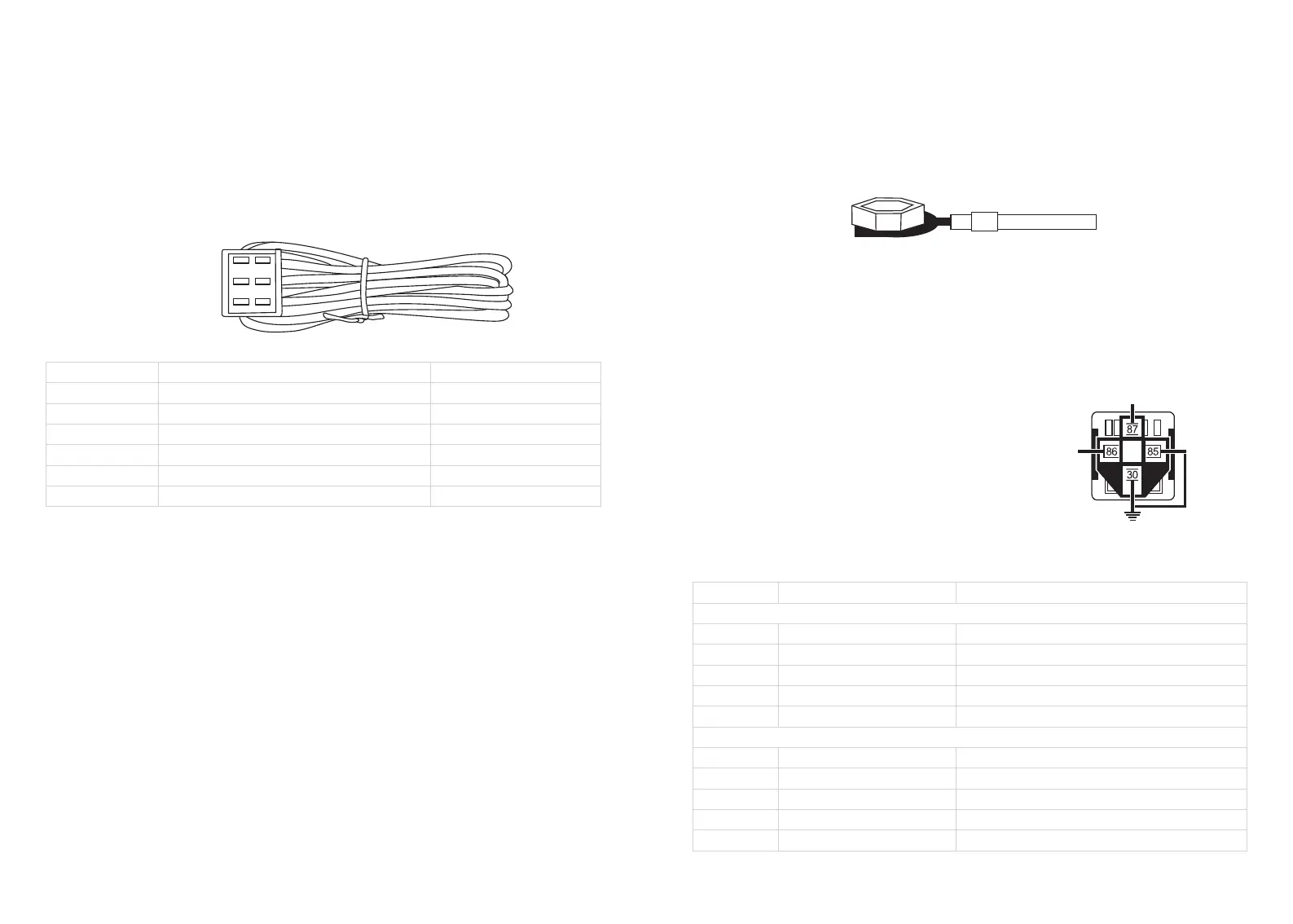
1.6-Pin ignition wire harness
Wire colors
Yellow
Brown
Red
White
Blue
Black
Wire usage
Connect with starter wire
Connect with ignition 2 wire
Connect with constant +12V
Connect with ignition 1 wire
Connect with Accessory(ACC)
Connect with chassis ground
Remark
See note 6
See note 3,4
See note 1
See note 2,4
See note 5,7
See note 8
NOTE (1-7):
1.Connect all the +12V wire in your vehicle ignition wire harness with the +12V red wires in ec003;
2.White ignition 1 wire: When turn the key to ACC or ON position, this wire with electricity, when
starting the car, this wire still with electricity;
3.Brown ignition 2 wire: When turn the key to ACC or ON position, this wire with electricity, when
starting the car, this wire will cut off power suddenly at the moment of starting the vehicle;
Once the vehicle is started, both white & brown wires are with electricity.
4.If there is only one ignition wire in your ignition wire harness, connect it with the white ignition 1 wire
in ec003, no need to connect the brown ignition 2 wire
5.If there are 2 ACC wire in your ignition harness, connect both ACC wires with blue ACC wire in ec003
6.If there are 2 starter wires in your ignition harness, connect both starter wires with yellow starter wire
in ec003.
7. If your car is newer cars that’s no ACC (only ON & OFF), connect the ignition 1 wire in your vehicle
with ACC wire & ignition 1 wire from ec003.
We recommend that you do not use a factory ground. Ground all your components including the siren, to
the same point in the vehicle, (preferably the kick panel). Scrape away any paint and use a factory bolt or
make your own ground with a self-tapping screw and a star washer.
Please use a factory bolt or screw to attach all the black chassis ground wires securely as the photo
show as below:
Note 8
Wiring method of black chassis ground wire
Factory bolt chassis ground wire
GWR(-)( Ground while running) wire connection
If there is chip immobilizer in your factory OEM key fob, you should also need to add an extra bypass
module in order to make this device work properly. For most of the bypass module, which require a
GWR(-) (ground while running wire), and you can use an extra SPST relay to generate a GWR wire.
Method is as below:
Note 9:
connect with GWR(-) from bypass module
Connect with EC003
ACC or ignition 1
(ACC is recommend)
connect with chassis ground(GND)
You can also use a SPDT relay to generate
but no need to connect 87a on SPDT relay.
a GWR wire and wiring method is the same
-08-
© EASYGUARD Electronics. All right reserved.
-07-
© EASYGUARD Electronics. All right reserved.
10P wire harness
Wire colors
The first row 5-pin wire
White/black
Brown
Brown
Orange
Blue
The 2nd Row 5-pin wire harness
White
Red/black
Green
Pink
Gray
Wire usage
Lock wire(-300mA)
Turn signal light/parking light(+)
Turn signal light/parking light(+)
Foot brake wire(+)
Negative door trigger switch(-)
Unlock control wire(-300mA)
Trunk release(-300mA)
Fuel pump wire(+)
Siren(-)
Hand brake wire(-)
Remark
Type B, see note 10 & central door locking connection
Type B, see central door locking connection
See note 11
See note 13
See note 12