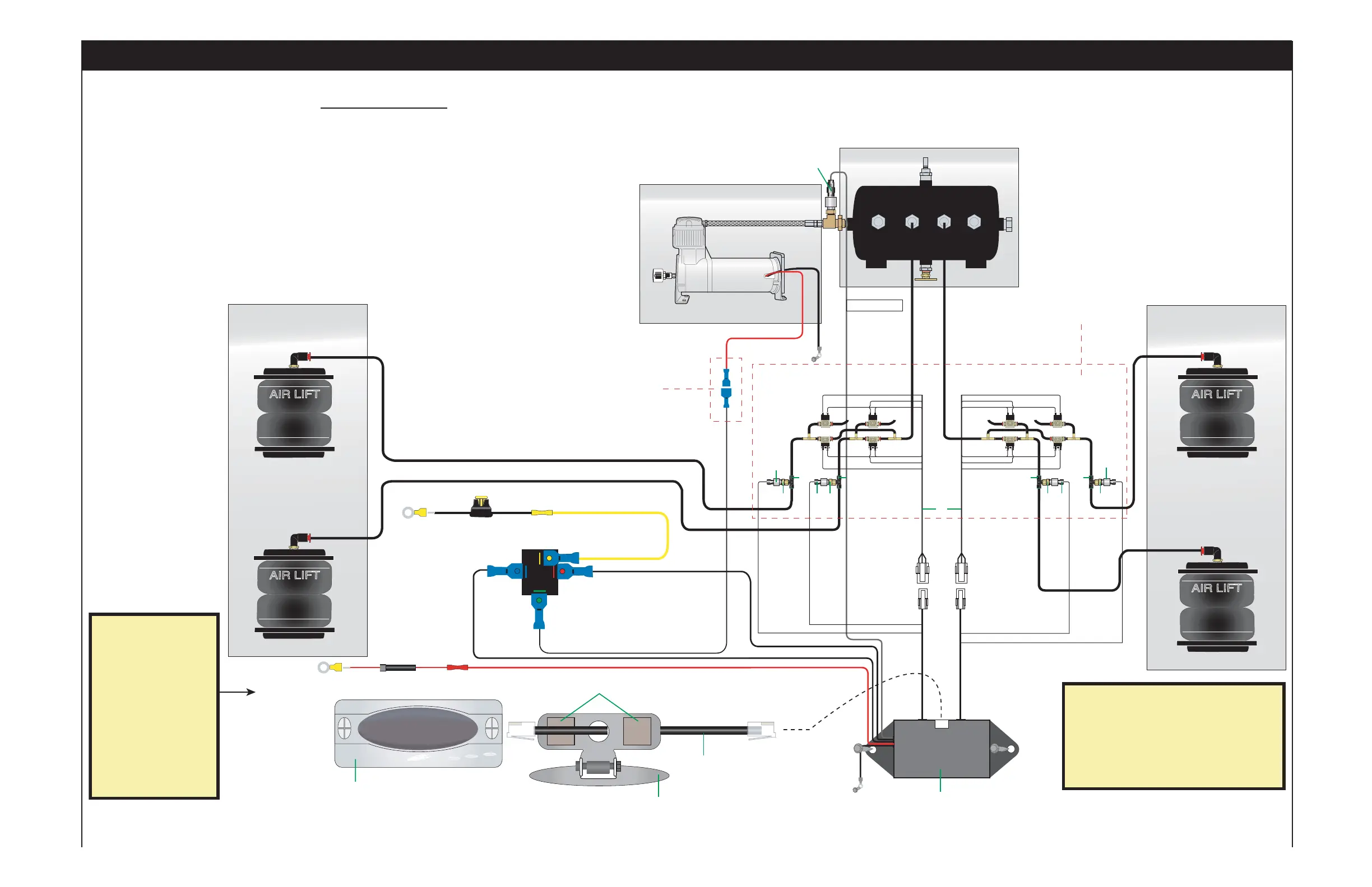
REAR
RIGHT
LEFT
LEFT
RIGHT
For Reference Only
Not included in kit
For Reference Only
Not included in kit
Display Mounting BracketDisplay Mounting Bracket
For Reference Only
Not included in kit
For Reference Only
Not included in kit
For Reference Only
Not included in kit
For Reference Only
Not included in kit
For Reference Only
Not included in kit
For Reference Only
Not included in kit
DisplayDisplay
FRONT
GND
REAR
F2
F1
R2
R1
FRONT
Compressor (OUT) (7)Compressor (OUT) (7)
To +12 Volt
Power Source
To +12 Volt
Power Source
30 AMP30 AMP
Back ViewBack View
3030
86868585
8787
To +12 Volt DC
Accessory
Power Source
To +12 Volt DC
Accessory
Power Source
GroundGround
5 AMP5 AMP
FRONT
Remove compressor
wire from pressure
sensor and connect to
wire coming from #87
of the relay.
See Figure 7 on
page 5 for further detail.
Transducer Wire
Left Right Left Right
Exhaust
Fill
REAR
Exhaust
Fill
CC
AA
DD
AA
EE
FF
BB
JJ
CC
II
JJ
CC
II
JJ
CC
II
JJ
CC
II
IMPORTANT
:
Power to the ECU must
connect to an accessory
source. The accessory
source powers the radio,
sunroof and other items
powered through the
accessory circuit and NOT
the ignition circuit. Failure
to connect to an accessory
source WILL CAUSE THE
DISPLAY TO FAIL and will
void the warranty.
IMPORTANT
:
Power to the ECU must
connect to an accessory
source. The accessory
source powers the radio,
sunroof and other items
powered through the
accessory circuit and NOT
the ignition circuit. Failure
to connect to an accessory
source WILL CAUSE THE
DISPLAY TO FAIL and will
void the warranty.
IMPORTANT
:
Valves cannot be grounded to the chassis. They
must be grounded using the harness ground in
order to properly complete the circuit. Failure to
follow these instructions will result in premature
FAILURE OF THE SYSTEM and will void the
warranty.
IMPORTANT
:
Valves cannot be grounded to the chassis. They
must be grounded using the harness ground in
order to properly complete the circuit. Failure to
follow these instructions will result in premature
FAILURE OF THE SYSTEM and will void the
warranty.
Installing the Digital Controller
Kit Diagram
Installing the Digital Controller
5
6
Figure 6
Item Part No. Description Quantity
A 25000 Digital Control ECU/Harness 1
B 27025 Digital Controller 1
C 24001 Pressure Transducer 5
D 26440 ECU/Display Cable 1
E 10415 Display Mounting Bracket 1
F 10519 Velcro 1
H 23586 Thread Sealant 1
I 21735 1/8 x 3/8 Bushing 4
J 21932 Branch Tee 4
Hardware List
 Loading...