33OPERATION AND INSTALLATION INSTRUCTIONS MN280075EN July 2018
Form 6 microprocessor-based rack-mount recloser control
TRIP CLOSE
FORM 6 RECLOSER CONTROL
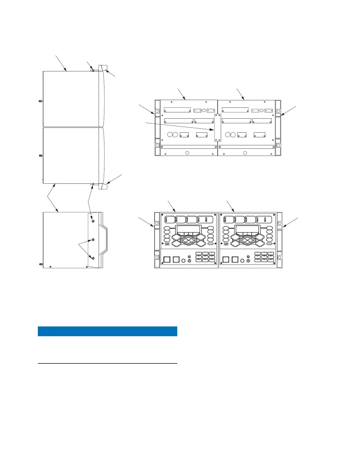
Left Side View
Front View
Top View
1
1
2
2
3
3
2
3
TRIP CLOSE
1
2
Back View with Connecting Plate
2
2
1
1
1
4
Figure28. Form 6 double rack mount recloser control
Secure the controls together
Connecting two Form 6 rack mount recloser controls
requires removing the front panel from the control (right-
side) as shown in Figure29.
NOTICE
Equipment damage. Always wear a grounding wrist
strap to control static electricity before handling circuit
boards. Failure to use this strap may result in circuit
board damage. T253.1
1. Unscrew the six screws from the control front panel
until they detach from the control box.
2. Pull the right side of the right control front panel out
towards the left (Figure29).
ote:N Various connecting wires will keep the panel attached
to the control (Figure29). It is not necessary to
disconnect any wires.
3. Use a long flathead screwdriver to screw each
#10-24 screw (Item 5, Table12) right to left into the
pre-threaded holes (Figure29).
ote:N It is not necessary to remove the front cover panel of
the left control.
4. Tighten screws completely (Figure29).
5. Gently place the front cover panel back onto
thecontrol.
6. Re-screw the screws back into the right control
front panel and tighten all hardware completely. Do
nottorque.
 Loading...


